


30
Altai Technologies Ltd. All rights reserved
AX500 Series Installation Manual
9.
Power Options and Cable Connection Instructions
You can follow one of the options below to power up the AX500 unit.
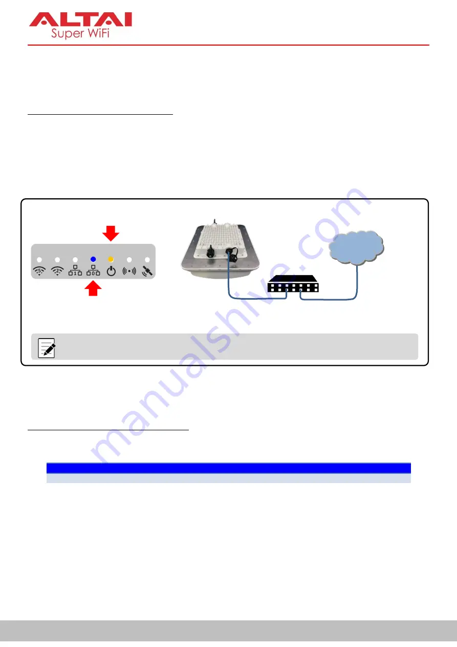
Option 1: 802.3at-Compliant PoE switch
1.
Connect Eth0 (PoE) port of the AX500 unit to an 802.3at PoE switch with an Ethernet cable.
2.
Make sure the Power LED light is yellow/green and the LAN LED light is blue/green.
3.
Make sure the cable length between the AX500 unit and the PoE switch
SHOULD NOT
exceed 100
meters.
Figure 9-1 Power Option 1 for AX500 Unit – 802.3at PoE Switch
Option 2: PoE Injector (Ordered Separately)
1.
Connect the PoE injector ports as described below via Ethernet Cables.
PoE Injector Ports
-
PoE
Go to AX500 Eth0 (PoE) port
-
LAN
Go to backend device such as switch or router, or computer, or peripherals
2.
Connect the PoE Injector to AC power socket using a power cord (Not provided in the package).
3.
Make sure the Power LED light is yellow/green and the LAN LED light is blue/green.
4.
Make sure the cable length between the AX500 unit and the backend device
SHOULD NOT
exceed 100
meters.
802.3at – Compliant
PoE Switch
LAN
AX500
Series AP
Ethernet Cable
(PoE + Data)
Ethernet Cable
(Data)
Note:
The AP shown in the diagram is for illustration purpose only. This connection option
applies to ALL AX500 Series AP Models including AX500-S, AX500-T and AX500-X
.
Blue (1000M)
/Green (100M)
Yellow (Standalone AP)
/Green (Thin AP)


