IP VarioBell
- installation and operating instructions
15
1.4 Connection of the IP-VarioBell
The IP-VarioBell consists of the basic board, processor board and it
always has two buttons on the board. Number of used call buttons is defined
with the used front panel plate. You can connect up to 85 call buttons to the
basic board and also a keypad. The basic board also includes two inputs (door
sensors or exit buttons) and two relay switches.
1.4.1 IP-VarioBell basic board
The basic board is the same for all models of the IP-VarioBell. It only
differs with included or excluded colour camera module. In the basic
configuration there is always a PoE module included (according to IEEE802.3af
norm), also there is a connector for connecting expansion modules, LED
illumination of a name card, reader of MicroSD cards and two relay switches.
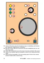
All operational and connected parts are marked with a digit inside a red
circle.
1.
CPU board (proccessor module)
2.
LED green
– powering of the doorphone works fine
3.
LED for checking of network activity, green = 100M LAN connected, yellow
= data transmission on the LAN
4.
Slot for a MicroSD card
– insert the card before powering the doorphone.
Never take out the card during doorphone´s operation!
5.
DIP switch
1
– always is
ON
position
(used for factory service only)
2
–
OFF
. In case it is in
ON
position when you
power the unit, the doorphone goes to a default
IP address 192.168.1.250 and also to its default style (a rescue
mode). The user name is
admin
and the access password is
1234
. To display a video stream, the user name is
video
and the
password is
1234
(if it is required). The operation position of the
DIP switch 2 is
OFF.
6.
Connection of the UTP cable (Ethernet, LAN, network)
7.
Two inputs (the middle connector is common for both inputs) for door
sensors or exit buttons (programmable, need to be ordered in production in
advance before delivery)
8.
Connection of
cable K0
for expansion module(s)
– a flat cable, on one side
there is an orange connector, on the other side there is a black connector
9.
Terminal connector of the switching contact of
the first relay
(NC =
normally closed, NO=normally open and COM=common, the middle
connector)
10.
Terminal connector of the switching contact of
the second relay
NO=normally open and COM= common, the middle connector)
Содержание IP-VarioBell IPVB-00
Страница 2: ...Installation and operating instructions ...
Страница 3: ...IP VarioBell User instructions 3 ...
Страница 17: ...IP VarioBell installation and operating instructions 17 ...
Страница 24: ...IP VarioBell installation and operating instructions 24 ...
Страница 28: ...IP VarioBell installation and operating instructions 28 2 Installation 2 1 Assembly ...
Страница 30: ...IP VarioBell installation and operating instructions 30 Placing the IP VarioBell doorphone on the wall ...
Страница 32: ...IP VarioBell installation and operating instructions 32 ...
Страница 89: ......
Страница 91: ... Alphatech Technologies s r o 2014 2016 version V3 5 ...


