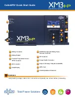
1. After wiring battery cable kit, battery sense cables and PTS, as shown in
Section 1, verify DC breaker is OFF.
2. Connect the Smart AlphaGuard (SAG) wire harness to SAG port (11). If no
SAG is installed, connect battery sense harness to the transponder (6).
3. Connect Precision Temperature Sensor to the PTS connector (3).
4. Connect the RF cable and the tamper switch to the transponder.
5. Verify the SPI / ALT Box Switch is in the ALT position.
6. Connect the SPI / ALT Box input cable to the Output 1 Connector (9). If 2nd
SPI / ALT Box is present connect input cable to Output 2 Connector.
7. Connect the LRI to the XM3. For existing LRI installations, use LRI adapter
kit, p/n 875-952-20.
8. Turn ON AC breaker and verify it is the correct utility voltage at the outlet (per
unit’s nameplate voltage). If correct, plug in the line cord into the utility outlet.
9. Verify correct battery voltage and polarity on battery cable connector with a
digital voltmeter, if correct plug into Inverter Module (1).
10. Turn battery breaker ON.
11. Verify no alarms are present after power up initialization. Wait for alarms to
clear (approximately 60 seconds).
12. If no alarms are present, proceed to Step 16.
13. If alarms are present and do not clear after 60 seconds, press the softkey with
ALM (C) to see the ACTIVE ALARM list for the menu item.
14. Press UP (
↑
) or DOWN (
↓
) to select the alarm of interest.
15. Press ENTR to select the alarm and display diagnostic information. Press
ESC to return to the alarm list.
16. On the SmartDisplay, press the BATT softkey, enter the BATT CONFIG
menu and select BATT MODEL and NUM BATT STRINGS (
Fig. 2
).
17. On the SmartDisplay, press BATT softkey, enter BATT CONFIG, enter BATT
MHOs* and DATE Code (
Fig. 3
).
*Note: Battery MHOs and Date code can only be set after DOCSIS
transponder has registered with CMTS. Please wait 3 minutes after
power up to enter Battery MHOs measurements.
18. Switch SPI / ALT Box Switch to ON, verifying the load on the XM3.
19. Perform a self-test by pressing and holding the Test Button (H) for 1-2
seconds. Wait for self-test completion before proceeding.
20. Perform standby test by shutting OFF utility breaker and verifying it goes into
STANDY MODE and supports the load.
21. Reapply AC power and verify the unit transfers to LINE MODE.
XM3-918HP
90V/0.4A
**ACTIvE ALARM**
OK
PWR
PM
BATT
ALM
COMM
OK
APPS
F
G
OUTPUT LED (green)
SOLID = Operation Normal
FLASHING = Minor Alarm
OFF = Major Alarm
ALARM LED (red)
FLASHING = Major Alarm
OFF = Minor Alarm
OFF = Operation Normal
F
G
H
H
SELF TEST BUTTON
Press button to initiate self test.
Installation Procedure
4. Power Module Configuration
XM3-918HP
90v/10.0A
OPERATION NORMAL
OK
ALM
OK
OK
PWR
BATT
COMM
APPS
Indicates
Model
and
Output voltage/Current
Softkeys
(Menu driven
system configuration)
A
A
B
Describes
Power Supply
Mode of Operation
Describes
Status of Functions
C
E
E
C
D
Functionality
top level menu
PWR, BATT, COMM and APPS
D
B
EDIT USING
hi 8
<ESC>
BATT MODEL
OTHER
ENTR
h
i
ESC
BATT
A1
DATE
1/10
hi
ADJUST vALUE
ENTR to shift field
ENTR
h
i
ESC
Fig. 2 - Battery Model input
Fig. 3 - Battery DATE Code and MHOs input
BATT
A1
MHOs
1000M
hi
ADJUST vALUE
ENTR to save
ENTR
h
i
ESC
CAUTION!
Before applying power, verify power supply rating is matched to AC input utility. Verify a low-resistance ground is
installed in accordance with the NEC
(refer to CableUPS Power Supply technical manual for details)
.


