2. INSTALLATION
21
6.
Install the upper bracket on to the UPS.
2.3
Wall Mounting (Continued)
Figure 2.9
Wall Mount Bracket
7.
Lift the UPS and rest it on top of the lower bracket installed in Step 5.
WARNING: The UPS is heavy. Use proper lifting techniques.
8.
Use the tapping screws to attach the upper bracket of the UPS to the wood
mounting board.
9.
Attach the lower bracket to the UPS.
10. If an external battery pack (EBP) is being installed, mount it to the wall in
the same way as the UPS module. Connect the EBP to the UPS using the
EBP connector cable.
11. Connect the UPS as shown in Section 2.5.
Multipurpose Bracket
Positioned for Wall
Mounting
4. COMMUNICATION
40
4.1
Interface Port (Continued)
4.1.2
RS-232 Connection
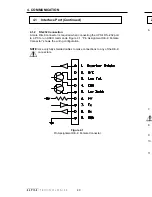
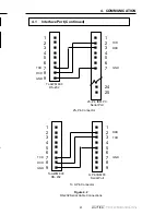
A male DE–9 connector is required when connecting the UPS's RS–232 port
to a PC to run ASCII commands. Figure 4.1, “Pin Assignment DE–9 Female
Connector” shows the wiring configuration.
NOTE: Use only fully shielded cables to make connections to any of the DE–9
connectors.
Figure 4.1
Pin Assignment DE–9 Female Connector


