background image

2.  INSTALLATION

20

2.3

Wall Mounting

Tools Required:

Masking tape

Drill and drill bits for pilot holes

Mounting hardware kit (included with unit)

Install the UPS on a 1.25 inch (3 cm) thick wood mounting board. Attach the
wood mounting board securely to the wall so that it can safely support the
UPSs weight. Four #12 x 1.25 inch tapping screws are supplied for attaching
the UPS to the wood mounting board.

The UPS requires 6 inches (15 cm) of clearance on the rear panel side for

ventilation and cable connections, and 7 inches (18 cm) of clearance on the
front panel side for internal battery replacement.

Install the UPS so its AC input cord can reach a grounded power outlet and

make sure the cords connecting the loads are long enough to reach the

loads.

The UPS can be mounted with the front panel facing right or left but the

internal batteries are easier to remove if the front panel is facing right.

1.

Place the mounting template on the wood mounting board with the top of
the template facing up.

2.

Use a level to align the template at the template leveling line. Use masking
tape to temporarily secure the template to the wood mounting board.

3.

Drill four pilot holes through the template at the screw locations marked 

S in

the template.

4.

Remove the template.

5.

Use the tapping screws to install the lower bracket onto the wood mounting
board. Level the top surface of the mounting bracket and tighten the

screws.

Requires

 Phillips Screwdriver

4.  COMMUNICATION

41

4.1

Interface Port (Continued)

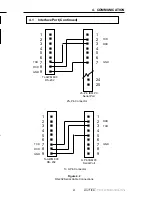
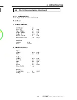
Figure 4.2

RS-232 Serial Cable Connections

n

n

n

n

n

n

n

n

n

n

1

n

2

n

3

n

4

n

5

n

6

n

7

n

8

n

9

To AWM 600

RS–232

9–Pin IBM PC

Serial Port

TXD

RXD

TXD

GND

GND

1
2
3
4
5
6
7
8
9

RXD

To 9-Pin Connector

25–Pin Connector

n

24

n

25

To AWM 600

RS–232

25–Pin IBM PC

Serial Port

TXD

RXD

GND

n

1

n

2

n

3

n

4

n

5

n

6

n

7

n

n

n

n

n

n

n

n

n

TXD

RXD

GND

1
2
3
4
5
6
7
8
9

Содержание NEXSYS 1250

Страница 1: ...F R O M A L P H A T E C H N O L O G I E S Nexsys System 600 900 1250 U N I N T E R R U P T I B L E P O W E R S U P P L I E S Operator s Manual 99 ld ...

Страница 2: ...lified personnel only DANGEROUS VOLTAGE A dangerous voltage exists in this area Use extreme caution ATTENTION Important operating instructions Follow these instructions closely WARNING Toreducetheriskoffireandshockhazards donotexpose this unit to rain or moisture WARNING Total Earth ground leakage current of loads connected to this UPS are not to exceed 3 1 mA i SAVE THESE INSTRUCTIONS This manual...

Страница 3: ...ice charge the UPS batteries at least once every 3 months to ensure optimum performance and battery life Install the UPS in a well ventilated area that is free of dust and mois ture Before installing the UPS verify the voltage requirements of the equipment to be protected load the AC input to the UPS line and the output voltage of the UPS The utility service panel should be equipped with a circuit...

Страница 4: ...e batteries with batteries of identical type and rating Never install old or untested batteries Do not use uninsulated tools or other conductive materials when handling batteries or working inside the UPS Remove all rings watches and other jewellery before servicing batteries Proper disposal of batteries is required Refer to local regulations for disposal procedures KEEP THESE INSTRUCTIONS THE NEX...

Страница 5: ...ernal Battery Pack 25 3 OPERATION 26 3 1 Operating Modes 26 3 2 Starting and Testing the UPS 28 3 3 Shutting Down the UPS 29 3 4 Self Test 30 3 5 Front Panel Indicators and Controls 31 4 COMMUNICATION 39 4 1 Interface Port 39 4 2 RS 232 Communication 42 5 MAINTENANCE 49 5 1 Maintenance 49 5 2 Run time Testing 49 5 3 Internal Battery Replacement 50 5 4 Troubleshooting 53 5 5 Repair Instructions 54 ...

Страница 6: ...o the loads The external battery pack can be joined to the UPS u Wall Mount Installation The Nexsys UPS mounts easily on a wall adjacent to key systems The external battery pack can be wall mounted near the UPS u Rack Mount Installation The Nexsys UPS mounts easily in a standard equipment rack to provide power to other modules in the rack The external battery pack can also be rack mounted u Expand...

Страница 7: ...nel overlay label One wall mounting template Four 12 tapping screws for wall mounting the UPS 4 Any other ordered options SAVE THE ORIGINAL SHIPPING CONTAINER If the UPS needs to be returned to the manufacturer for service package it in its original shipping container If the original container is not available make sure that the unit is packed with at least three inches of shock absorbing material...

Страница 8: ... or optional terminal blocks and a serial interface alarm connector to facilitate your most demanding power and communication needs 1 3 A Tour of the Nexsys UPS 1 4 Nexsys UPS Front Panel Control and Display Panel The control and display panel shows vital operating information about the UPS and allows the operator to invoke a self test to confirm proper operation On Off Switch This switch controls...

Страница 9: ...able to connect the UPS to the computer is available from Alpha Technologies The part numbers for the cables are 870 540 21 Cable Assembly Nexsys PC RS 232 DE 9M to DB 25F 870 540 22 Cable Assembly Nexsys PC RS 232 DE 9M to DE 9F Input Output Receptacle Plate The standard Nexsys UPS comes with an input output receptacle plate with the following AC Input Circuit Breaker The AC input circuit breaker...

Страница 10: ...Input Circuit Breaker AC Output Receptacles Cooling fans External Battery Pack EBP Connector Communication Alarm Interface Connector External Battery Connector UPS AC Line Cord Connector Nameplate Label 5 The unit The with By f prov The vari of th UPS batt Dur ove batt the be u To d at le man on t not Pro 5 ...

Страница 11: ...irements A qualified electrician should inspect the existing wiring in the building prior to installation to verify proper grounding Use the external ground lug on the UPS s rear panel if required Standby Generators The UPS is equipped with a frequency sense circuit along with a frequency synchronization circuit to optimize operation with most standby generators Prior to installation compare the o...

Страница 12: ...ires Phillips Screwdriver Figure 2 1 Rubber Feet 2 Install the multipurpose bracket as a seismic bracket on both sides of the UPS Figure 2 2 Seismic Bracket 3 Stick the adhesive side of the horizontal layout overlay label over the control and display panel to make reading the control and display panel easier Make sure that the label is properly aligned 4 Connect the UPS as shown in Section 2 5 Rub...

Страница 13: ...P 3 Loosen but do not remove the remaining UPS and EBP front panel screws 4 Slide the braces behind the EBP front panel and chassis at the upper and lower screw holes where the screws have been removed Align the slots of the braces with the screw holes and insert the screws Adjust the braces so that they are aligned parallel to the top and bottom chassis surfaces Tighten the screws 2 2 Tower Confi...

Страница 14: ... the UPS so that the EBP braces slide between the UPS front panel and chassis Align the braces with the UPS upper and lower screw holes Insert and tighten the screws 6 Tighten all the other screws on the UPS and EBP front panels Figure 2 4 Front Installation Brace 4 4 2 Cur Mai 1 U 2 I ...

Страница 15: ... 2 Tower Configuration Installation Continued 7 Install two other braces to the outside of the UPS and EBP rear panels using the screws shipped with the EBP Braces EBP Connector Cable Figure 2 5 Rear Installation EBP UPS ...

Страница 16: ...combination to act as seismic brackets 9 Connect the UPS to the EBP using the EBP connector cable 10 Connect the UPS as shown in Section 2 5 2 2 Tower Configuration Installation Continued Multipurpose Bracket as a Seismic Bracket Figure 2 6 Seismic Bracket 4 4 2 The be a men of th Figu thro are 4 2 ...

Страница 17: ...sive backed rubber pads to the bottom of the UPS and EBP chassis about 1 inch 25 mm from the corners Figure 2 7 Adhesive Backed Rubber Pads 2 Stack the UPS on top of the EBP or vice versa WARNING Do not place the UPS and EBP on a surface that is unable to fully support their combined weight Figure 2 8 Bench Top Laying 3 Connect the UPS as shown in Section 2 5 Adhesive Backed Rubber Pads a ...

Страница 18: ... AC input cord can reach a grounded power outlet and make sure the cords connecting the loads are long enough to reach the loads The UPS can be mounted with the front panel facing right or left but the internal batteries are easier to remove if the front panel is facing right 1 Place the mounting template on the wood mounting board with the top of the template facing up 2 Use a level to align the ...

Страница 19: ... Use proper lifting techniques 8 Use the tapping screws to attach the upper bracket of the UPS to the wood mounting board 9 Attach the lower bracket to the UPS 10 If an external battery pack EBP is being installed mount it to the wall in the same way as the UPS module Connect the EBP to the UPS using the EBP connector cable 11 Connect the UPS as shown in Section 2 5 Multipurpose Bracket Positioned...

Страница 20: ...e mounted flush with the front panel in the 23 inch rack configuration A thicker multipurpose bracket is available from Alpha Technologies for that purpose Figure 2 10 Rack Mounting 2 Lift the UPS into position and secure the brackets to the rack WARNING The unit is heavy Use proper lifting techniques 3 If an external battery pack EBP is being installed mount it to the rack in the same way as the ...

Страница 21: ...ceed 3 1 mA 1 Connect the UPS to utility line AC power 2 If required connect the external battery EBP to the UPS using the connector cable 3 Start and test the UPS as shown in Section 3 2 Figure 2 11 Rear Panel Connections External Battery Pack Connector External Battery Pack EBP AC Output Receptacles Communication Alarm Connector AC Line Power Cord Connector External Battery Pack Cable ...

Страница 22: ...st be done by qualified technicians only The wiring must conform to applicable electrical codes Make sure that the main utility panel is shut off before proceeding 1 Connect the input wires to the input terminal block Use 14 AWG 2 0 mm2 wiring and torque the screws to 35 in lb 4 0 N m 2 Start and test the UPS without a load connected as described in Section 3 2 3 Shut off the UPS and connect the o...

Страница 23: ... charge times without sacrificing battery life S E M I T N U R Y R E T T A B S E M I T N U R Y R E T T A B S E M I T N U R Y R E T T A B S E M I T N U R Y R E T T A B S E M I T N U R Y R E T T A B S P U l e d o M l e d o M P B E y r e t t a B e g a t l o V C D V l a n r e t n I s e i r e t t a B y l n O n i m h P B E 1 n i m h s P B E 2 n i m h s P B E 3 n i m h s P B E 4 n i m h s P B E 5 n i m h...

Страница 24: ...S s On Battery Mode has three different states as the battery is discharged See Figure 3 1 Low Battery Mode States 1 Low Battery Warning State The UPS automatically switches into this state when it is in On Battery mode The battery has enough power to keep the loads running but it is almost discharged and cannot supply the loads for much longer In this state the Display and Control Panel s Low Bat...

Страница 25: ...hes into this state when it is in On Battery mode and the battery is discharged to a level where it cannot provide power to the UPS s internal electronics In this state all the Display and Control panel s LED s are off indicating the UPS is shut down and providing no power to the loads It stays in this state until utility line AC power is available 3 1 Operating Modes Continued Battery Voltage UPS...

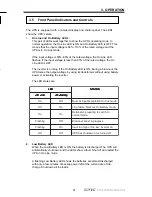
Страница 26: ...itched back into On Line mode 4 After the UPS is tested one at a time switch on the loads Press the Load button to turn on the power meter and observe the front panel Load LEDs As each additional load is switched on the LEDs will display the increased load WARNING Do not run the UPS when the 110 LED is ON The UPS is overloaded Standby Mode In this mode the UPS output power is shut off but its cont...

Страница 27: ...ATION 29 Turn off all loads connected to the UPS Turn off the UPS On Off switch Unplug the UPS s AC line cord from the wall receptacle 3 3 Shutting Down the UPS 2 3 1 Figure 3 2 UPS Shutdown Procedures 3 1 2 ...

Страница 28: ...n the UPS s output 1 If the On Line LED is ON start the self test by pressing down the Test button for three seconds The UPS should transfer to battery power without affecting the load The On Battery and Test LEDs should come ON and the audible alarm should beep once every 30 seconds 2 It takes about one minute to finish the test then the UPS returns to On Line mode without affecting the load 3 Th...

Страница 29: ...ry LED is ON the battery is discharged The UPS will automatically shut down and the LEDs show a fault Shut off and restart the UPS in On Line mode A flashing Low Battery LED shows the batteries are almost discharged with only a few minutes of backup power left at the current rate of dis charge Shut down all the loads D E L D E L D E L D E L D E L S U T A T S S U T A T S S U T A T S S U T A T S S U...

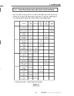
Страница 30: ...temperature has exceeded the maximum allowed Input frequency the UPS can operate only within 3 Hz of the rated input frequency see the label on the UPS and the input power frequency is not within that range Alarms Temperature warning the battery temperature is high and approaching the maximum allowed or is too low for proper battery operation PLL Fault unstable input power has repeatedly prevented...

Страница 31: ... r o h S N O g n i h s a l F y r e t t a B w o L e g a t l o V N O N O y r e t t a B h g i H e g a t l o V N O g n i h s a l F t u p t u O h g i H e g a t l o V N O N O t u p t u O o N e g a t l o V N O g n i h s a l F h g i H e r u t a r e p m e T N O N O e g a t t a W h g i H N O g n i h s a l F S M R A L A e n i L y c n e u q e r F g n i h s a l F N O L L P g n i h s a l F g n i h s a l F d a o...

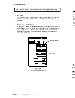
Страница 32: ...r as a percentage of the UPS s maximum output power It can be operated at any power up to 100 but should not be used when the 110 LED is ON Overloading can result in reduced runtime unexpected shutdowns or damage to the inverter 4 Test LED The Test LED comes ON when the UPS is in the Test mode The Test LED flashes when an Output Shutdown or Inverter Shutdown command is pending Figure 3 6 Load Stat...

Страница 33: ...tery The LEDs show the percent battery voltage between fully charged and discharged levels NOTE Batteries that cannot be fully charged should be serviced or replaced Test the runtime annually using the procedure in Section 5 2 Runtime Testing to ensure that the batteries can hold an acceptable charge Figure 3 7 Battery Charge Indicator Button Battery Button ...

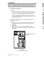
Страница 34: ...mit a continuous sound In this case pressing the Mute button will not disable the beeper Shut off the UPS and correct the fault Pressing and holding this button has two different results depending on what mode the UPS is in B Test When the UPS is in On Line mode pressing down this button for three seconds starts the self test See Section 3 4 Self Test for more information C Manual Start When the U...

Страница 35: ... AC power is present B The UPS is in On Battery mode and shuts down because of low battery charge C The UPS is in On Battery mode and is shut down by an RS 232 Inverter Off command D The UPS is in either On Line or On Battery Mode and is shut down by an RS 232 Output Shutdown command The UPS stays latched in this mode until an RS 232 Output Shutdown Inactive command is received If utility line AC ...

Страница 36: ...e The UPS does not switch between Boost On Line or On Battery mode even if the utility line conditions change D To exit Hot Swap mode after installing the internal batteries simultainously press and hold the Mute and Batt buttons for at least three seconds After exiting Hot Swap mode the four lower LEDs stop flashing and the UPS resumes normal operation See Section 5 3 Internal Battery Replacement...

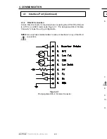
Страница 37: ...ine is out of tolerance e g On Battery mode except in Test mode Pin 4 COM Common for Pin 3 and 5 This is the common signal for Line Fail and Low Battery alarm signals This pin is not internally connected to the logic ground If required the connection to the logic ground should be provided externally Pin 5 Low Batt Low Battery Alarm N O 10 mA maximum This opto isolated open collector pin and COM Pi...

Страница 38: ...connector is required when connecting the UPS s RS 232 port to a PC to run ASCII commands Figure 4 1 Pin Assignment DE 9 Female Connector shows the wiring configuration NOTE Use only fully shielded cables to make connections to any of the DE 9 connectors Figure 4 1 Pin Assignment DE 9 Female Connector ...

Страница 39: ... n n n n 1 n 2 n 3 n 4 n 5 n 6 n 7 n 8 n 9 To AWM 600 RS 232 9 Pin IBM PC Serial Port TXD RXD TXD GND GND 1 2 3 4 5 6 7 8 9 RXD To 9 Pin Connector 25 Pin Connector n 24 n 25 To AWM 600 RS 232 25 Pin IBM PC Serial Port TXD RXD GND n 1 n 2 n 3 n 4 n 5 n 6 n 7 n n n n n n n n n TXD RXD GND 1 2 3 4 5 6 7 8 9 ...

Страница 40: ...rocomm to communi cate with the UPS use the following setup NOTE The Back Space and Delete keys are ignored by the program If a command is typed in incorrectly press Enter and type the command again Microsoft Windows can also be used to set up these parameters Windows 3 x Click the Terminal icon Windows 95 or Windows 98 path Start Programs Accessories Communica tions Hyperterminal e p y T n o i t ...

Страница 41: ...arms Figure 4 3 shows the opening menu screen which displays menu Option 1 through 4 Current line status output status faults and alarms if any exist are also displayed Alpha Technologies NEXSYS 0 Main Menu 1 Unit Specification 2 Input Output Values 3 Maintenance 4 Calibration Line Status Output Status Faults Alarms Figure 4 3 Main Menu Screen 4 2 3 Communication Setup g n i k a h s d n a H f f o ...

Страница 42: ...e to fault Shutdown due to low battery Shutdown due to user request Shutdown due to no line Faults Vout_Abs Output voltage absent Output short circuit Vout_Hi Output voltage high Vbat_Hi Battery voltage high Vbat_Lo Battery voltage low Temp_Hi Ambient temperature high Iout_Hi Output current high EEPROM_Flt Error reading EEPROM Wout_Hi Output power high overload Alarms Vout_Lo Output voltage low Io...

Страница 43: ...tz Input Voltage xxx volts Output Voltage xxx volts Output VA xxxx VA Battery Voltage xx volts Max Chgr Current x xx amps EEPROM Version xx xx Date xx xx xx 2 Input Output Values Input Voltage xxx x volts Freq xx x hertz Output Voltage xxx x volts Current xx x amps Freq xx x hertz VA xxx VA Power xxx watts Power Factor x xx Battery Temperature xx deg C Voltage xx x volts 45 ...

Страница 44: ... Low Lmt 077 42 Slow Detect High Hyst 108 43 Slow Detect Low Hyst 082 44 Slow Detect Boost High 096 45 Slow Detect Boost Low 088 46 Bat charge current 3 00 4 2 6 Input Output Values Input Voltage The voltage measured at the input of the UPS e g 120 VAC Frequency The frequency of the AC Line measured at the input of the UPS e g 60 Hz Output Voltage Output Voltage displays the true RMS voltage at th...

Страница 45: ...rtment Battery Voltage Voltage indicates the average DC voltage of UPS batteries 4 2 8 Maintenance Maintenance allows you to start the test mode and shut down the output Battery test options A self test can be initiated or cancelled by selecting this menu The test duration can be set in steps of 0 5 seconds The default is 120 steps which equals 60 seconds Output Shutdown The output of the unit can...

Страница 46: ...ce sustained overvoltage by lowering the overvoltage detection level NOTE The Slow Detect Hi Hys Ref should also be adjusted by the same amount Slow Detect Lo Lmt Increasing this value makes the UPS more sensitive to a slow low amplitude line disturbance brownout by raising the brownout detection level NOTE The Slow Detect Lo Hys Ref should also be adjusted by the same amount Slow Detect Lo Hyst I...

Страница 47: ...atteries reach this peak they will slowly lose capacity and eventually will be unable to provide the required backup power To determine the maximum amount of battery run time available run this test at least once a year The length of the test varies from several minutes to many hours and should not be done while critical loads are running depending on the UPS s output This test discharges the batt...

Страница 48: ...f cracks leaks or swelling and always replace them with batteries of identical type and rating Never install old or untested batteries Order batteries from Alpha Technologies The batteries are hot swappable They can be changed without shutting off the UPS Procedure For all models 1 If the UPS has an external battery pack attached and is running properly go to Step 3 2 Switch the UPS into Hot Swap ...

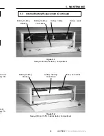
Страница 49: ...cement Continued Figure 5 1 Nexsys 600 Internal Battery Compartment Battery Leads Battery Holding Bracket Battery Cables Battery Holding Foam Block Figure 5 2 Nexsys 900 and 1250 Internal Battery Compartment Battery Connectors Battery Holding Bracket Battery Holding Foam Block ...

Страница 50: ...the chassis 7 Slide the new batteries into the UPS until the batteries are sticking out about 2 inches 5 cm 8 Attach the battery cable connectors to the battery tabs of the new batteries The red cable should be attached to the positive tab and the black cable to the negative tab 9 Slide the batteries all the way in and position the filler foam block 10 Reinstall the battery holding bracket and its...

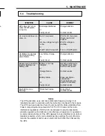
Страница 51: ...ircuit other than that used by the UPS SYMPTOM CAUSE REMEDY UPS does not turn on when On Off switch turned on Discharged batteries or Faulty circuit Charge batteries Contact vendor On Line mode does not come on No AC line power or AC line voltage too high or low or On Off switch turned off Wait for AC line power Check input circuit breaker Wait for voltage to stablilize Turn on On Off switch On Ba...

Страница 52: ...ipping container For other shipping instructions see Section 1 2 Unpacking and Inspection Alpha Technologies does not assume responsibility for damage caused by improper packaging of returned units United States 360 647 2360 Canada 604 430 1476 United Kingdom 44 1279 422110 Germany 49 9122 997303 Middle East 357 5 375675 Australia 61 0 2 894 7866 To obtain complete technical support 7 days week 24...

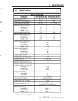
Страница 53: ...p y T 0 2 1 0 3 2 A t n e r r u C t u p t u O m u m i x a M 0 0 6 s y s x e N 0 0 9 s y s x e N 0 5 2 1 s y s x e N 0 5 5 7 0 0 1 6 2 9 3 4 5 A V r e w o P t n e r a p p A t u p t u O 0 0 6 s y s x e N 0 0 9 s y s x e N 0 5 2 1 s y s x e N 0 0 6 0 0 9 0 5 2 1 W r e w o P e v i t c A t u p t u O 0 0 6 s y s x e N 0 0 9 s y s x e N 0 5 2 1 s y s x e N 0 2 4 0 3 6 5 7 8 n o i t a l u g e R t u p t u ...

Страница 54: ...N EBP417 24N EBP417 48N 50 23 78 36 78 36 s e i r e t t a B l a n r e t n I S P U s e i r e t t a B l a n r e t n I S P U s e i r e t t a B l a n r e t n I S P U s e i r e t t a B l a n r e t n I S P U s e i r e t t a B l a n r e t n I S P U y t i c a p a C d n a e p y T y r e t t a B 0 0 6 s y s x e N 0 0 9 s y s x e N 0 5 2 1 s y s x e N d e t a l u g e r e v l a v d e l a e s e e r f e c n a n ...

Страница 55: ...een damaged due to one of these causes or if the unit is free of defects a handling or repair fee may be assessed prior to returning the unit WITH RESPECT TO BATTERIES PERIPHERAL DEVICES ATTACHMENTS OR APPARATUS NOT MANUFACTURED BY ALPHA TECHNOLOGIES ALPHA WILL ASSIGN TO THE PURCHASER ITS RIGHTS UNDER THE ORIGINAL MANUFACTURER S WARRANTY OF SUCH BATTERIES PERIPHERAL DEVICES ATTACHMENTS OR APPARATU...

Страница 56: ...ill be present at the UPS output To prevent the possibility of injury to service or emergency personnel always shut off the UPS power switch to de energize the circuit EMERGENCY SHUTDOWN PROCEDURE 1 Shut off the UPS On Off switch 2 Unplug the AC line cord from the wall receptacle If the AC input is hardwired into the unit switch off the UPS main panel AC breaker EMERGENCY SHUTDOWN Shut off On Off ...

Страница 57: ...pha Technologies Hansastrasse 8 D 91126 Schwabach Tel 49 9122 997303 Fax 49 9122 997321 MIDDLE EAST Alphatec P O Box 6468 3307 Limassol Cyprus Tel 357 5 375675 Fax 357 5 359595 Alpha sales and service offices located throughout the world http www alpha us com CANADA Alpha Technologies 7033 Antrim Ave Burnaby BC V5J 4M5 Tel 604 430 1476 Fax 604 430 8908 AUSTRALIA Alpha Technologies 8 Anella Ave Uni...

Отзывы: