Your Power Solutions Partner
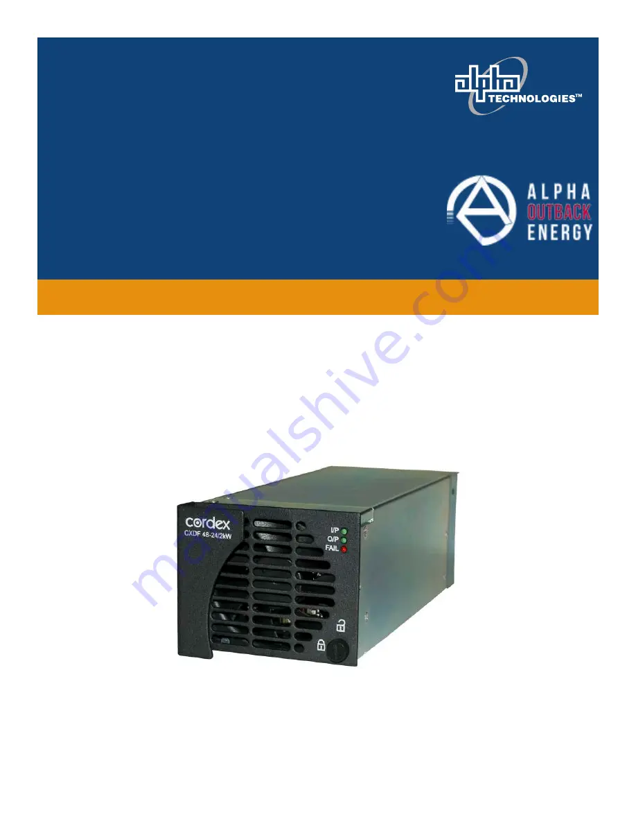
Cordex DC/DC Converter
CXDF 48-24/2kW, 48V In – 24V Out
Installation & Operation Manual
Part # 012-527-B2
Effective:
07/2020
Страница 1: ...Your Power Solutions Partner Cordex DC DC Converter CXDF 48 24 2kW 48V In 24V Out Installation Operation Manual Part 012 527 B2 Effective 07 2020 ...
Страница 2: ......
Страница 3: ...affect the placement of equipment and or installation procedures NOTE A NOTE provides additional information to help complete a specific task or procedure CAUTION CAUTION indicates safety information intended to PREVENT DAMAGE to material or equipment Cautions are designated with a shock hazard icon the word CAUTION and a rule beneath which the information appears WARNING WARNING presents safety i...
Страница 4: ...allation or removal procedure Ensure that no liquids or wet clothes come into contact with internal components Hazardous electrically live parts inside this unit are energized from the batteries even when the AC input power is disconnected Battery Safety Servicing and connection of batteries must be performed by or under the direct supervision of personnel knowledgeable of batteries and the requir...
Страница 5: ... NOTA NOTE provee información adicional para ayudar a completar una tarea o un procedimiento específico CUIDADO CUIDADO CAUTION indica información de seguridad con el propósito de PREVENIR DAÑOS al material o al equipo Los avisos de cuidado están designados con un icono de peligro de choque la palabra CUIDADO y una línea debajo de la cual aparece la información ADVERTENCIA Una ADVERTENCIA WARNING ...
Страница 6: ... de instalación o remoción Asegúrese de que ningún líquido ni ropa húmeda en contacto con los componentes internos Las partes eléctricamente activas peligrosas dentro de esta unidad están energizadas por las baterías incluso cuando se desconecta la alimentación de entrada de CA Seguridad de la Batería Externa El mantenimiento y la conexión de las baterías debe ser realizado por o bajo la supervisi...
Страница 7: ...e procédure spécifique PRUDENCE Le symbole PRUDENCE CAUTION indique une information de sécurité destinée à ÉVITER DES DOMMAGES au matériel ou à l équipement Ce symbole est représenté par une icône de danger de décharge électrique le terme PRUDENCE et une ligne en dessous de laquelle l information est affichée AVERTISSEMENT Le symbole AVERTISSEMENT WARNING donne des informations sur la sécurité per...
Страница 8: ... n entre en contact avec les composants internes Les pièces électriques dangereuses à l intérieur de cette unité sont alimentées par les batteries même lorsque l alimentation CA en entrée est débranchée Sécurité de la Batterie L entretien et la connexion des batteries doivent être effectués par un spécialiste des batteries ou sous la supervision directe d un tel spécialiste en prenant les précauti...
Страница 9: ...stimmte Aufgabe zu lösen bzw ein bestimmtes Verfahren durchzuführen Hinweise sind mit einem Häkchen dem Wort HINWEIS und einem Strich unter dem die Informationen aufgeführt sind gekennzeichnet ACHTUNG ACHTUNG CAUTION kennzeichnet Sicherheitsinformationen die darauf abzielen SCHÄDEN an Materialien oder Geräten ZU VERHINDERN Diese Warnhinweise sind mit einem gelben Warndreieck dem Wort ACHTUNG und e...
Страница 10: ...e Kleidungsstücke mit innenliegenden Komponenten in Berührung kommen Gefährliche stromführende Teile innerhalb dieses Geräts werden auch bei Trennung der Netzverbindung noch über die Batterien versorgt Batteriesicherheit Die Wartung und der Anschluss von Batterien muss von Mitarbeitern durchgeführt bzw direkt beaufsichtigt werden die über Kenntnisse über Batterien und die erforderlichen Sicherheit...
Страница 11: ... 2 Tools Required 8 4 3 Shelf Preparation Mounting 8 4 4 Converter Module Insertion Removal 8 4 5 CXCI CXCI Installation 9 5 WIRING AND CONNECTIONS 12 5 1 Safety Precautions 12 5 2 Calculating Wire Size Requirements 12 5 3 Input Output Connections 12 5 4 CAN Serial Ports 13 5 5 Network Connection and Remote Communications via CXCI CXCI 13 5 6 Signal Wiring Connections for CXCI CXCI 14 6 SYSTEM STA...
Страница 12: ...ate removal 9 Figure 5 Showing CXCI controller module installation 10 Figure 6 Baffle and pem removal 10 Figure 7 Showing CXCI Module Preparation 11 Figure 8 Showing CXCI module installation 11 Figure 9 Showing relay connections 14 Figure 10 Showing digital input connection method 14 Figure 11 Location of LVD bypass jumper 19 Figure 12 Showing CXCI original design replacement detail 20 Figure 13 C...
Страница 13: ...and isolated 24 Volt DC output from a 48 Volt DC input Each module is a stand alone converter element which plugs into a common shelf The shelf provides external connections for input output and alarm interfaces Additional converter modules can increase the current capacity and redundancy of the converter system Figure 1 Perspective view of CXDF 48 24 2kW converter module The converter system cons...
Страница 14: ... 840 20 may be equipped with one CXCI CXCI controller and up to four CXDF 48 24 2kW converters List 0 19 rack 6 offset mounting List 19 23 rack 6 offset mounting List 24 Charcoal finish with white contrasting silkscreen List 56 Positive I P ground negative O P ground List 80 Positive I P ground positive O P ground List 81 Output adapters DC cable right angle List 82 Module blank plate List 90 CXCI...
Страница 15: ... operational status of the module see Table 1 Indicator Color Associated Condition Green I P DC INPUT OK Green O P Converter Module Power ON Red FAIL Converter Module FAIL Red FAIL flashing Converter Minor Alarm Table 1 Module indicators and conditions 2 1 3 Regulation and Paralleling Cordex modular converters use output slope or regulation offset to accomplish load sharing When the converters are...
Страница 16: ...oller operation are provided in the current version software manual The data logging feature allows the user to capture data from multiple inputs for AC DC voltages load battery current cell voltages temperatures automatically for up to 16 user defined logs Typical applications of the CXCI CXCI logging include power system details thermal performance of outdoor enclosures battery cell specifics or...
Страница 17: ...irmware application the red LED is illuminated 2 3 2 Reset A reset button is located on the front panel for restarting the CXCI CXCI microprocessor Refer also to the software manual always select the Reset menu item before pressing the reset button 2 3 3 Modem Port not available on the CXCI list 98 The Modem port front panel DB 9 connector Figure 2 is designed for connection to Alpha Technologies ...
Страница 18: ...d temperature compensation temp comp or room ambient temperature A voltage is supplied to these terminals to power the temperature sensors 2 5 Digital Input Channels The CXCI CXCI can accommodate up to two channels and can monitor digital alarm control signals from converters rectifiers and many other types of equipment 2 6 Alarm and Control Output Relays The CXCI CXCI contains four 4 Form C digit...
Страница 19: ...iginal shipping container If the original container is unavailable make sure the product is packed with at least three inches of shock absorbing material to prevent shipping damage NOTE Alpha Technologies is not responsible for damage caused by the improper packaging of returned products 3 2 Check for Damage Prior to unpacking the product note any damage to the shipping container Unpack the produc...
Страница 20: ...ds Cutters and wire strippers Crimping tool optional for large gauge wire Socket and ratchet set Imperial measure 4 3 Shelf Preparation Mounting WARNING This system is designed to be installed in a restricted access location that is inaccessible to the general public The 030 840 20 shelf has been designed for flush mounting in a 19 relay rack The 030 901 20 shelf has been designed for flush mounti...
Страница 21: ... to the Maintenance chapter for the CXCI CXCI replacement procedure 4 5 1 CXCI CXCI Blank Plate Removal Remove the converter in the left most position in order to access the side of the CXCI CXCI where the mounting screws are located Figure 4 Showing CXCI CXCI blank plate removal 4 5 2 CXCI CXCI Module Installation 4 5 2 1 Installing a CXCI Controller Module 1 Remove the blank plate as described p...
Страница 22: ...module installation 4 5 2 2 Installing a CXCI Controller Module 1 Remove blank plate as described previously 2 Remove baffle via front mounting screw if you have not already done so Figure 6 Baffle and pem removal 3 Follow the steps in Figure 7 and Figure 8 to complete the installation Remove pem before installation Remove front mounting screw to release baffle Baffle and pem removed ...
Страница 23: ... panel Apply pressure on the module baffle plate to engage the rear connector in the shelf receptacle Gently remove LCD circuit Install by placing the CXCI module on the shelf bottom and sliding the module into the rear connector inside of the shelf Install front mounting screw to secure body of CXCI module Remove two 2 side mounting screws to release the CXCI front panel ...
Страница 24: ...quirement CMA A x LF x K AVD where CMA Cross section of wire in circular mil area A Ultimate drain in amps LF Conductor loop feet K 11 1 constant factor for commercial TW type copper wire AVD Allowable voltage drop Check again that the ampacity rating of the cable meets the requirement for the installation application Consult local electrical codes NEC CEC etc for guidelines If required increase t...
Страница 25: ... closest to the CAN ports 5 5 Network Connection and Remote Communications via CXCI CXCI The Cordex system can be set up monitored and tested via Ethernet 10 100 Base T serial data connection The communication protocol supports a web interface Some standard scenarios are described below 5 5 1 Modem Port not available on the CXCI list 98 The Modem port front panel DB 9 connector Figure 2 is designe...
Страница 26: ...e during an alarm condition see CXC Software manual When the CXCI CXCI reset button is pressed or power is lost all relays de energize 5 6 2 Digital Inputs The digital input channels factory installed are used to monitor various alarm and control signals All input channels are voltage activated and accept a bipolar i e negative or positive DC signal directly D1 and D2 on TB12 are available for cus...
Страница 27: ... all input cable terminations The analog input channels are used to monitor various types of electrical signals 5 6 3 1 Voltage Voltage Input 1 load voltage per CXC software terminals V1 on the shelf provide connections to an optional secondary voltage input Voltage Input 2 battery voltage per CXC software is wired internally V2 to the output voltage of the shelf This is used as the reference for ...
Страница 28: ...ad Voltage and Converter Load Current by default Average Conv Output Voltage and Total Conv Output Current are used respectively 6 3 1 Load Current in a Rectifier Converter System For proper operation of Charge Current Control and Power Save the system load current must include the current drawn from the rectifiers used to power the converters Depending on the location of the current shunt in the ...
Страница 29: ...CXCI CXCI IP Address Reset To reset the IP address press and hold the front panel reset button for three seconds The CXCI CXCI unit will beep three times IP will be reset to 10 10 10 201 and DHCP will be disabled The settings will be saved and the unit will then reset This will allow local access e g with a laptop and a standard network crossover cable See current version software manual for detai...
Страница 30: ... performing maintenance on the system s alarms and control settings Procedure Date Completed Clean ventilation openings Inspect all system connections re torque as necessary Verify alarm control settings Verify alarm relay operation Table 3 Sample maintenance log 7 1 Fan Replacement CAUTION Use fan assembly with correct connector as supplied by Alpha 1 Shut off the unit and unlatch rotate the fron...
Страница 31: ...tion then JP2 pins 1 and 2 must be shorted together to maintain LVD operation If the LVD is controlled on NO contacts then JP2 pins 2 and 3 must be shorted together NOTE bypassing the LVD generates an alarm Figure 11 Location of LVD bypass jumper 6 Disconnect the DB signal connector from the CXCI at the rear of the shelf 7 Ensure converter is in the right most position 8 Remove converter in the le...
Страница 32: ... Installation chapter remove the pem etc and then continue with the next steps regarding the CXC CXCI configuration 11 Replace the DB connector on the back of the CXCI CXCI 12 Log on to the CXC and go to Logs and Files Manage Configuration File Upload Site Configuration and select the saved cfg file After the upload do a Submit Changes Make sure the site information is checked to save it and click...
Страница 33: ...tes an alarm 6 Disconnect the DB signal connector from the CXCI at the rear of the shelf 7 Ensure a converter is in the right most position Remove the converter in the left most position in order to access the side of the CXCI CXCI where the mounting screws are located 8 Place the CXCI controller module on the shelf bottom and slide into the rear connector at the back of the slot Figure 13 Cordex ...
Страница 34: ...ost position Remove the converter in the left most position in order to access the side of the CXCI CXCI where the mounting screws are located 8 Remove four 4 mounting screws from the CXCI The first two screws will release the front panel from the controller circuit board to expose the third screw that releases the LCD circuit board Carefully remove the LCD board to expose the fourth and final scr...
Страница 35: ...failure due to cause s external to the unit including but not limited to environmental conditions water damage power surges or any other external influence The customer is responsible for all shipping and handling charges Where products are covered under warranty AOE will pay the cost of shipping the repaired or replacement unit back to the customer 8 2 Battery Warranty Note that battery warranty ...
Страница 36: ...HCP Dynamic host configuration protocol EMC Electromagnetic compatibility EMI Electromagnetic interference ESD Electrostatic discharge FCC Federal Communications Commission for the USA IP Internet protocol LED Light emitting diode LVD Low voltage disconnect NC Normally closed NEC National Electrical Code for the USA NO Normally open OSHA Occupational Safety Health Administration OVP Over voltage p...
Страница 37: ...1 line 1 0 0 1 load Dynamic Regulation 2 deviation for 50 to 100 load step settling to 0 1 in 2 ms Time Stability 0 1 per year Temperature Stability 100 ppm C Electrical Noise 38 dBrnC voice band 20 mVRMS 10 kHz to 10 MHz wideband 150 mVp p 10 kHz to 100 MHz Acoustic Noise 60 dBa at 1m 3 ft Module Indicators DC Input OK LED green Module ON LED green Alarm Module Fail LED red major red flashing min...
Страница 38: ...al Temperature 40 to 55 C 40 to 131 F standard operating derated operation to 65 C 149 F 40 to 70 C 40 to 158 F storage Humidity 0 to 95 non condensing Elevation 500 to 2800 m 1640 to 9186 ft Standards Compliance This product is designed to meet or exceed the following FCC 47 CFR part 15 Class A radiated and conducted EMI EN 55022 CISPR 22 Class A radiated and conducted EMI ENV 50204 Radiated elec...
Страница 39: ...see drawing at the rear of this manual Communications CAN bus RJ 12 offset OUT and IN side access Recommended Disconnect Device and Wire Sizing 19 Shelf Input Wire Size minimum 19 Dual Feed 150 A breaker or fuse 1AWG per feed 90 C rated 60 C 2x 1AWG common Output Wire Size minimum 19 Shelf 2x 1 0 90 C rated Recommended Disconnect Device and Wire Sizing 23 Dual Input Shelf Input Wire Size minimum F...
Страница 40: ...cordance with FCC requirements we provide the following statement as specified in the FCC guidelines for conformance to Part 15 Class B Warning The CXCI has been tested and found to comply with the limits for a Class B digital device pursuant to part 15 of the FCC Rules These limits are designed to provide reasonable protection against harmful interference in a residential installation This equipm...
Страница 41: ...s to this equipment not expressly described in this manual could void the FCC compliance Environmental Temperature 40 to 65 C standard 3000m derate to 55 C 4000m 40 to 149 F derate to 131 F 13124ft Humidity 0 to 95 non condensing Elevation 500 to 4000m 1640 to 13124 ft Hardware Specifications CXCI CXCI CPU Coldfire Display 4 digit LCD Front Panel Controls Display pushbutton toggle switch for volta...
Страница 42: ... version 2 10 minimum Recommended Signal Wire Sizes as per UL CSA Wire Size Range 0 14 to 1 50mm 2 26 to 16 AWG Temperature Range 0 to 50 C 32 to 122 F CAUTION TO REDUCE RISK OF FIRE USE ONLY 0 14mm 2 26 AWG OR LARGER WIRE The above information is valid at the time of publication Consult factory for up to date ordering information Specifications are subject to change without notice ...
Страница 43: ... DUAl INPUT 030 840 06 SHEET NTS REV B 1 1 ITEM QTY 2010 11 WH List 80 81 added BP00735 B MP JK DESCRIPTION LTR APPD DATE DWN REVISIONS CHKD 0 18 0 0 71 20 0 0 79 324 0 12 76 332 0 13 07 0 0 11 9 0 47 59 8 2 35 39 9 1 57 65 3 2 57 126 2 4 97 151 6 5 97 188 0 7 40 203 8 8 02 215 8 8 50 241 2 9 50 253 2 9 97 269 1 10 59 305 3 12 02 330 7 13 02 465 0 18 31 0 566 7 22 31 6 1 0 24 31 5 1 24 37 9 1 49 5...
Страница 44: ...ED 48V INPUT FEED B MODS 3 4 MAX CURRENT 110A MAX CURRENT 110A FEED A MODS 1 2 24V OUTPUT 48V INPUT GND O P GND I P 1 4 20 x 1 2 HEX BOLTS AND WASHERS SUPPLIED 48V INPUT FEED B MODS 3 4 MAX CURRENT 110A 25 1 13 14 J8 24 FUNCTION NOT CONNECTED CAN OUT RJ12 OFFSET J7 J8 J7 T1 23 V1 22 D2 2 21 D1 2 20 K4 NC 19 K4 NO 18 K3 COM 17 9 CTS 8 NOT CONNECTED 6 NOT CONNECTED 5 CAN L 4 NOT CONNECTED 3 CAN H 2 ...
Страница 45: ... 5M 1994 0 05 1 0 01 0 005 OF SCALE REV SHEET SIZE DWG NO TITLE TYPE A NTS D2 B 1 1 030 901 06 OUTLINE SHELF 23 5 MDL CXDF 48 24V DUAL INPUT DESCRIPTION LTR APPD DATE DWN REVISIONS CHKD 1 49 37 9 0 0 0 00 6 1 0 24 2 24 56 9 3 24 82 3 88 4 3 48 566 0 22 28 0 18 0 0 71 20 0 0 79 324 0 12 76 331 5 13 05 0 0 11 9 0 47 59 5 2 34 91 5 3 60 116 9 4 60 177 7 7 00 203 1 8 00 239 5 9 43 255 4 10 05 267 3 10...
Страница 46: ...CTS 9 18 K3 COM 17 K4 NC 19 K4 NO 3 NOT CONNECTED 4 CAN L 5 NOT CONNECTED 6 NOT CONNECTED 8 23 V1 22 D2 2 21 D1 2 20 7 RX 6 NOT CONNECTED 8 NOT CONNECTED DSR 7 TX 3 RX 2 DCD 1 FUNCTION RTS RI I1 25 T2 T1 24 COM 6 4 DTR 5 48V INPUT NOT CONNECTED PIN FUNCTION 15 K2 NC 16 K2 NO TX 2 TX 3 RX 4 5 NOT CONNECTED MODULE 3 5 FEED B CXCI CXCI DB 25 PIN FUNCTION 1 K1 COM 2 K1 NC 3 K2 COM 4 K3 NC 5 K3 NO 6 K4...
Страница 47: ... P1 S501 P100 S502 P1 S503 P100 S504 P1 S505 P100 S506 P1 S507 P100 S508 P1 S509 P100 S510 P1 S511 P100 Assy201 Assy202 Assy203 Assy204 Assy205 E100 24V E101 24V E1 54V E4 54V E202 24V E203 24V E201 54V E200 54V S200 S300 S701 P202 S702 P201 S600 P203 PCB Leds FanConn CXDF 2kW A4 P N 707 637 20 LIST 0 SCHEMATIC 707 637 05 S400 P400 S601 E301 54V E300 54V E302 24V E303 24V CAN INTERFACE E100 24V E1...
Страница 48: ... DRAWN DESIGN MATERIAL FINISH FOR MANUFACTURING WITHOUT ITS WRITTEN CONSENT ARGUS TECHNOLOGIES AND SHALL NOT BE COPIED OR USED THESE DESIGNS AND SPECIFICATIONS ARE THE PROPERTY OF REVISIONS LTR DESCRIPTION APPD DATE REV X X 0 04 X XX 0 02 X XXX 0 01 X 1mm X X 0 5mm X XX 0 25mm 036 201 06 OUTLINE CTRLR I O TERM BLK 1 8kW SHELF CXCI PER P O and Doc 070 024 83 1 1 J K SDW 2006 04 2006 07 D2 c 2006 AR...
Страница 49: ...TOP VIEW WITH COVER REMOVED P2 JUMPER SETTINGS FOR LVD CONTROL INHIBIT FUNCTION SHORT PINS 1 AND 2 IF LVD CONTROLLED ON K1 NO CONTACTS TO MAINTAIN OPERATION SHORT PINS 2 AND 3 IF LVD CONTROLLED ON K1 NC CONTACTS TO MAINTAIN OPERATION 25 PIN CABLE ARGUS P N 877 499 10 ISOMETRIC VIEWS 1 2 3 P2 FRONT VIEW 13 1 25 14 DB25 PIN OUT 1 K1 COM 2 K1 NC 3 K2 COM 4 K3 NC 5 K3 NO 6 K4 COM 7 D1 1 8 D1 1 9 V1 10...
Страница 50: ......
Страница 51: ......
Страница 52: ...adquarter Germany Hansastrasse 8 D 91126 Schwabach Tel 49 9122 79889 0 Fax 49 9122 79889 21 Mail info alpha outback energy com France and Benelux fbnl alpha outback energy com Spain spain alpha outback energy com For more information please visit www alpha outback energy com Russia russia alpha outback energy com Africa africa alpha outback energy com Eastern Europe ee alpha outback energy com Mid...