


508115-01
Issue 2043
Page 41 of 57
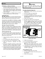
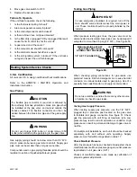
6.
If unit will be started immediately upon completion of
installation, prime trap per procedure outlined in Unit
Start-Up section.
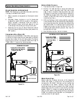
Condensate line must slope downward away from the
trap to drain. If drain level is above condensate trap,
condensate pump must be used. Condensate drain
line should be routed within the conditioned space to
avoid freezing of condensate and blockage of drain
line. If this is not possible, a heat cable kit may be used
on the condensate trap and line. Heating cable kit is
available from Allied in various lengths; 6 ft. (1.8m) - kit
no. 26K68 and 24 ft. (7.3m) - kit no. 26K69.
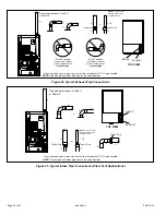
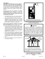
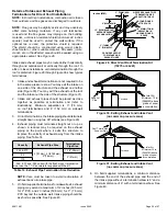
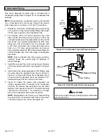
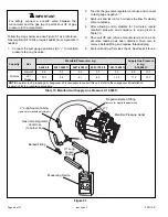
Figure 43. Condensate Trap Location
(shown with right side exit of condensation)
5’ max.
to drain
1” min.
2” max.
Trap can be installed a maximum
of 5ft. from furnace (*PVC only)
Field Provided Vent
1” min. 2” max. above
condensate drain.
*Piping from furnace must slope down a
minimum 1/4” per ft. toward trap
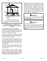
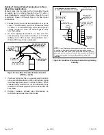
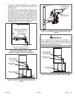
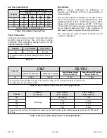
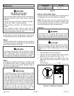
Figure 44. Unit with Cooling Coil Using Separate
Drain
Drain
Field Provided Vent
1” min. 2” max. above
condensate drain.
Condensate Drain
Connection
Evaporator Drain Line
(vent required)
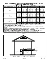
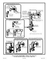
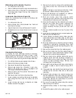
FurnaceCondensate
DrainConnection
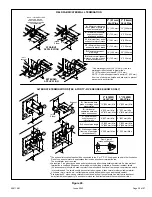
From Evaporator Coil
Optional
Field Provided Vent
1” min. 2” max. above
condensate drain.
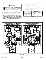
Figure 45.
Condensate Trap with Optional Overflow
Switch
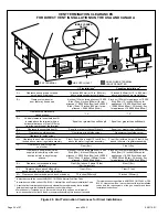
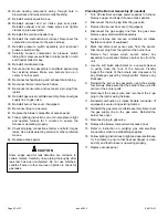
When combining the furnace and evaporator coil
drains together, the A/C condensate drain outlet must
be vented to relieve pressure in order for the furnace
pressure switch to operate properly.
IMPORTANT
Figure 46. Evaporator Coil Using a Common Drain
Field Provided Vent
1” min. 2” max. above
condensate drain.
Evaporator Drain Line
(vent required)
Condensate Drain
Connection