background image

Port Trunking

28

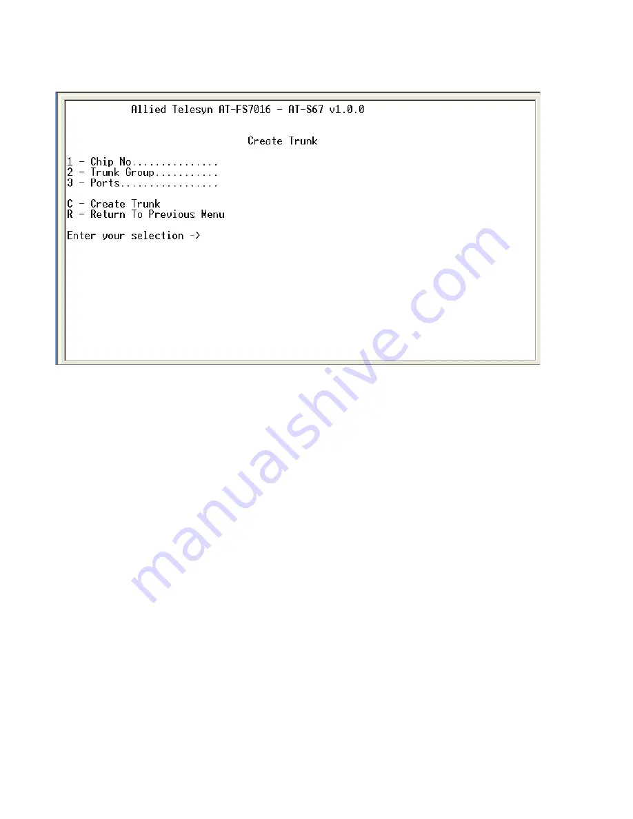
3. Type 1 to select Create Trunk. The Create Trunk Menu in Figure 10 is 

displayed.

Figure 10  Create Trunk Menu

4. Type 1 to select Chip No. One of the following prompts will be 

displayed:

For an AT-FS7016 switch:

Select Chip Number [1-2] ->

For an AT-FS7024 switch:

Select Chip Number [1-3] ->

The AT-FS7016 has two forwarding chips and the AT-FS7024 has 
3. Each forwarding chip contains 8 ports. For example, on the 
AT-FS7016, Ports 1 through 8 are controlled by Chip 1 and Ports 9 
through 16 are controlled by Chip 2. The trunking port cannot 
span across chips.

5. Select the chip number and press <Enter>.

Содержание AT-S67

Страница 1: ...Management Software AT S67 AT S68 User s Guide FOR USE WITH AT FS7016 AND AT FS7024 SMART SWITCHES VERSION 1 0 0 PN 613 50494 00 Rev A...

Страница 2: ...s mentioned herein are trademarks or registered trademarks of their respective owners Allied Telesyn Inc reserves the right to make changes in specifications and other information contained in this do...

Страница 3: ...hat You Think 9 Chapter 1 Getting Started 11 Overview 12 Starting a Local Management Session 13 Starting a Local Management Session 13 Using the Terminal Interface 15 Quitting from a Local Session 15...

Страница 4: ...a VLAN 56 Clearing All VLANs 58 Showing VLANs 59 Chapter 6 Quality of Service QoS 61 QoS Overview 62 Configuring Port based QoS 63 Resetting the QoS 66 Chapter 7 Switch Administration 67 Changing the...

Страница 5: ...ons on how to use and configure the AT S67 and AT S68 management software through the RS 232 Terminal Port to manage the AT FS7000 Series Smart Switches The AT FS7000 Series Smart Switches are availab...

Страница 6: ...ng and deleting VLANs Chapter 6 Quality of Service QoS describes QoS and also contains the procedure for adjusting the QoS parameters Chapter 7 Switch Administration contains the procedures for settin...

Страница 7: ...owing conventions Note Notes provide additional information Caution Cautions indicate that performing or omitting a specific action may result in equipment damage or loss of data Warning Warnings indi...

Страница 8: ...ur products All Allied Telesyn products can be downloaded from the web site in PDF format The following guide provides port specifications topologies installation instruction and troubleshooting infor...

Страница 9: ...lesyn com Returning Products Products for return or repair must first be assigned a Return Materials Authorization RMA number A product sent to Allied Telesyn without a RMA number will be returned to...

Страница 10: ......

Страница 11: ...provided information and instructions on how to start a local management session using the AT S67 or AT S68 management software This chapter contains the following sections Overview on page 12 Starti...

Страница 12: ...g parameters To change or adjust the operating parameters you must access the switch s management software You can create a local management session with an AT FS7016 or AT FS7024 Smart Switch by conn...

Страница 13: ...hernet traffic through the unit Starting a Local Management Session To start a local management session perform the following procedure 1 Connect one end of a straight through RS 232 cable with a DB 9...

Страница 14: ...an equivalent terminal emulation program 4 Press Enter twice 5 If prompted for a password enter the password for the management software The default password is friend To change the default password r...

Страница 15: ...m a Local Session To quit a local session type Q for Quit You should always be sure to exit from a management session when you are finished managing the switch This will prevent unauthorized changes t...

Страница 16: ......

Страница 17: ...is chapter contains procedures for viewing and changing the parameter settings for the individual ports on a switch This chapter contains the following sections Configuring Port Parameters on page 18...

Страница 18: ...You can only configure one port at a time 1 From the Main Menu type 1 to select Port Menu The Port Menu in Figure 3 is displayed Figure 3 Port Menu 2 From the Port Menu type 1 to select Port Configur...

Страница 19: ...ion You can also disable an unused port to secure if from unauthorized connections Enable port is the default setting 2 Flow Control When the port is operating in full duplex mode it will uses a speci...

Страница 20: ...isable twoadditionalparametersaredisplayedinthePortConfiguration Menu 4 Speed 10 MB 5 Duplex Half Duplex You use these two parameters to set the port s speed and duplex mode The possible setting for 4...

Страница 21: ...The information in this window is for viewing purposes only To change these parameters refer to Configuring Port Parameters on page 18 The parameters are described below Prt The port number on the sw...

Страница 22: ...duplex Half duplex indicates that the port is operating at half duplex mode Full duplex indicates that the port is operating at full duplex mode Flow The flow control setting for the port Flow control...

Страница 23: ...nformation and procedures for creating a port trunk This chapter contains the following sections Overview on page 24 Creating a Port Trunk on page 27 Deleting a Port Trunk on page 30 Displaying Port T...

Страница 24: ...AT FS7016 switches Figure 6 Port Trunk Example Port Trunking Guidelines Observe the following guidelines when creating a port trunk A port trunk can consist of 2 3 or 4 ports The ports of a trunk must...

Страница 25: ...switches On the first AT FS7024 switch you had chosen ports 12 13 14 and 15 for a trunk On the second AT FS7024 switch you had chosen ports 21 22 23 and 24 To maintain the order of the port connection...

Страница 26: ...rt on the switches until after you have configured the trunk with the management software Connecting the cables before configuring the software will create a loop in you network topology Data loops ca...

Страница 27: ...trunk perform the following procedure 1 From the Main Menu type 1 to select Port Menu The Port Menu as shown in Figure 3 on page 18 is displayed 2 From the Port Menu type 3 to select Port Trunking The...

Страница 28: ...For an AT FS7016 switch Select Chip Number 1 2 For an AT FS7024 switch Select Chip Number 1 3 The AT FS7016 has two forwarding chips and the AT FS7024 has 3 Each forwarding chip contains 8 ports For e...

Страница 29: ...an AT FS7024 switch Select Port Number 1 24 Note A trunk must have at least two ports designated 9 Type the number of the ports you wish to trunk and press Enter You can specify the ports individually...

Страница 30: ...gy Data loops can result in broadcast storms and poor network performance To delete a port trunk perform the following procedure 1 From the Main Menu type 1 to select Port Menu The Port Menu in Figure...

Страница 31: ...f the trunk group you wish to delete and press Enter The Delete Trunk Menu will be displayed showing the values for the Trunk Group Chip No and Ports 6 Type D to select Delete Trunk The following prom...

Страница 32: ...is displayed 2 From the Port Menu type 3 to select Port Trunking The Port Trunking Menu in Figure 9 on page 27 is displayed 3 Type 3 to select Show Trunks The Show Trunk Groups window in Figure 12 is...

Страница 33: ...displayed 2 From the Port Menu type 3 to select Port Trunking The Port Trunking Menu in Figure 9 on page 27 is displayed 3 Type 4 to select Reset Trunk Configuration The following prompt is displayed...

Страница 34: ......

Страница 35: ...ormation and procedures for creating a port mirror and advanced port mirroring This chapter contains the following sections Overview on page 36 Creating a Port Mirror on page 37 Deleting a Port Mirror...

Страница 36: ...the more ports you mirror the less likely the mirroring port will be able to handle all the traffic For example if you mirror the traffic of six heavily active ports the mirror port is likely to drop...

Страница 37: ...a port mirror perform the following procedure 1 From the Main Menu type 1 for Port Menu The Port Menu in Figure 3 on page 18 is displayed 2 From the Port Menu type 2 for Port Mirroring The Port Mirro...

Страница 38: ...to disable For an AT FS7024 switch Select port 1 24 0 to disable 5 Type the number of the port that will function as the mirror port the port where traffic will be copied and press Enter 6 Select one...

Страница 39: ...to be mirrored To mirror the traffic of more than one port enter the ports individually for example 1 5 7 or as a range for example 9 12 and press Enter You can also enter None to reset the port valu...

Страница 40: ...rt Mirroring Menu in Figure 13 on page 37 is displayed 3 Type1toselectDestinationMirrorPort Oneofthefollowingprompts will be displayed For an AT FS7016 switch Select port 1 16 0 to disable For an AT F...

Страница 41: ...rt Menu The Port Menu in Figure 3 on page 18 is displayed 2 From the Port Menu type 2 for Port Mirroring Menu The Port Mirroring Menu in Figure 13 on page 37 is displayed 3 Type 2 to select Advanced M...

Страница 42: ...ilter A All Frames D Dest Addr S Source Addr 7 Type your selection and press Enter 8 Type 2 to select Mirror MAC Address The following prompt is displayed Mirror Frames with MAC Address 9 Enter the MA...

Страница 43: ...s For example setting the Mirror Divider to 10 will mirror the frames in either the receive or transmit direction every 10 frames Thus the mirrored frame rate will be 1 out of every 10 frames of the s...

Страница 44: ......

Страница 45: ...ual Local Area Networks VLANs from a local management session This chapter contains the following sections VLAN Features on page 46 Overview of Port based VLANs on page 48 Creating a Port based VLAN o...

Страница 46: ...kets are sent to each and every individual port VLANs address the limitations of standard switch segmentation by containing broadcast as well as end node to end node traffic Grouping users into logica...

Страница 47: ...st frames to other members of the VLAN a network administrator can segment users requiring access to sensitive information into separate VLANs from the rest of the general user community Since data tr...

Страница 48: ...to a port based VLAN by the PVID assigned to the port on which the frame is received and forwards the frame only to those ports with the same PVID Consequently all the ports of a port based VLAN must...

Страница 49: ...7 and AT S68 management software The value is the same for all ports in a port based VLAN and is identical to the VLAN s VID except when using the special VLAN configuration feature If there are end n...

Страница 50: ...al LANs 50 Creating a Port based VLAN To create a port based VLAN perform the following procedure 1 From the Main Menu type 2 to select VLAN Menu The VLAN Menu in Figure 17 is displayed Figure 17 VLAN...

Страница 51: ...AT S67 and AT S68 User s Guide 51 2 From the VLAN Menu type 1 to select Configure VLANs The Configure VLANs Menu in Figure 18 is displayed Figure 18 Configure VLANs Menu...

Страница 52: ...following prompt is displayed Enter new value 1 to 26 Note A VLAN must have a VID 5 Press Enter 6 Type 2 to select Ports The following prompt is displayed Enter new value You can specify the port ind...

Страница 53: ...the following message is displayed SUCCESS Press any key to continue 9 Type S to select Save VLAN Configuration A port based VLAN has been created To create additional VLANs type R twice to return to...

Страница 54: ...Modify VLAN Menu in Figure 20 is displayed Figure 20 Modify VLAN Menu 3 Type 1 to select VLAN ID VID The VLAN ID is used to identify which VLAN you want to modify The following prompt is displayed En...

Страница 55: ...The following prompt is displayed Enter new value 6 Enter the new value and press Enter 7 Type M to select Modify VLAN 8 The following message is displayed Modifying VLAN Please wait 9 TypeStoselectSa...

Страница 56: ...enu type 2 to select VLAN Menu 2 From the VLAN Menu type 1 to select Configure VLANs The Configure VLANs Menu in Figure 18 on page 51 is displayed 3 From the Configure VLANs Menu type 3 to select Dele...

Страница 57: ...message is displayed Are you sure you want to delete this Vlan Y N 7 Type Y to delete the VLAN and press Enter 8 If Y is selected the following prompt is displayed Deleting VLAN Please wait Then SUCC...

Страница 58: ...select Configure VLANs The Configuring VLANs in Figure 18 on page 51 is displayed 3 Type 4 to select Clear All VLANs The following prompt is displayed Are you sure you want clear all VLANs Y N 4 Type...

Страница 59: ...re 1 From the Main Menu type 2 to select VLAN Menu The VLAN Menu as shown in Figure 17 on page 50 is displayed 2 FromtheVLANMenu type2toselectShowVLANs Anexampleofthe Show VLANs Menu is shown in Figur...

Страница 60: ......

Страница 61: ...This chapter contains procedures for configuring the Quality of Service QoS parameters of the switch This chapter contains the following sections QoS Overview on page 62 Configuring Port based QoS on...

Страница 62: ...is equal to or less than the TCI Threshold the frame will be sent to the low priority queue For example if the TCI Threshold is set to 5 incoming frames with a tag of 6 and above will be sent to the...

Страница 63: ...igure 23 is displayed Figure 23 QoS Menu 2 From the QoS Menu select 1 to enable port based QoS Note If QoS Enable Disable is disabled all tagged and untagged frames are placed in one queue on the swit...

Страница 64: ...if a tagged frame is sent to either a high priority queue or low priority queue The following prompt will be displayed Enter new value 1 to 8 8 Enter the new value and press Enter You will be returne...

Страница 65: ...r an AT FS7024 switch Enter Port Number 1 24 11 Enter the port number and press Enter The following prompt will be displayed Enter new value H High L Low 12 Type H or L to select the port priority 13...

Страница 66: ...Menu in Figure 23 on page 63 is displayed 2 Type 6 to select Reset QoS Settings The following prompt is displayed Do you really want to Reset Y es N o 3 Type Y to continue 4 You will be returned to t...

Страница 67: ...g the login password The login password enables the user to access the Main Menu to configure the management software This chapter also contains instructions for downloading a new application image Th...

Страница 68: ...ord perform the following procedure 1 From the Main Menu type 4 to select Administration Menu The Administration Menu in Figure 25 is displayed Figure 25 Administration Menu 2 From the Administration...

Страница 69: ...new password and press Enter The following prompt will be displayed Re enter New Password 5 Re enterthenewpasswordandpress Enter Thefollowingprompt will be displayed SUCCESS Password changed Press an...

Страница 70: ......

Страница 71: ...information and instructions for setting the MAC Aging time and resetting the switch to the factory defaults This chapter contains the following sections MAC Address Overview on page 72 Changing the M...

Страница 72: ...ss table determines the port where the destination end node is connected It then forwards the packet to the appropriate port and onto the end node This increases network bandwidth by limiting each fra...

Страница 73: ...frames from the end node over a specified period of time The switch assumes that the end node with that MAC address is not longer active and that its MAC address can be purged from the table This prev...

Страница 74: ...u type 5 to select System Config Menu The System Config Menu in Figure 26 is displayed Figure 26 System Config Menu 2 Type 1 to select MAC Aging Time The following prompt will be displayed Enter New V...

Страница 75: ...to select System Config Menu The System Config Menu in Figure 26 on page 74 is displayed 2 Type 2 to select Reset to Factory Defaults The following confirmation prompt will be displayed Do you want to...

Страница 76: ......

Страница 77: ...contains the procedures for displaying data traffic statistics per port and for the switch This chapter contains the following sections Displaying Port Statistics on page 78 Displaying Switch Statist...

Страница 78: ...ing Port Statistics To display the port statistics perform the following procedure 1 From the Main Menu type 6 to select Ethernet Statistics The Ethernet Statistics Menu in Figure 27 is displayed Figu...

Страница 79: ...arameters are described below Total Packets The total number of valid packets received and transmitted on the port TX Total Packets The total number of packets transmitted out the port RX Total Packet...

Страница 80: ...RR The number of packets with alignment errors received on the port RX Fragment The number of undersized packets received on the port RX Oversize The number of packets exceeding the maximum specified...

Страница 81: ...Statistics The Display Modular Statistics window in Figure 29 is displayed Figure 29 Display Modular Statistics Window The information in this window is for viewing purposes only The parameters are de...

Страница 82: ...with the proper length 64 1518 bytes received by the switch RX Alignment_ERR The number of packets with alignment errors received on the switch RX Fragment The number of undersized packets received o...

Страница 83: ...lowing procedure 1 From the Main Menu type 6 to select Ethernet Statistics The Ethernet Statistics Menu shown in Figure 27 on page 78 is displayed 2 Type 3 to select Clear Statistics The statistics fo...

Страница 84: ......

Страница 85: ...laying the firmware version of the management software running self test and dumping the software configurations This chapter contains the following sections Displaying the Firmware Version on page 86...

Страница 86: ...procedure 1 From the Main Menu type 8 to select Diagnostics The Diagnostics Menu in Figure 30 is displayed Figure 30 Diagnostics Menu 2 Type 1 to select Display Firmware Version A prompt will be disp...

Страница 87: ...ostics The Diagnostics Menu in Figure 30 on page 86 is displayed 2 Type 2 to select Self Test Status The Show Self Test Status window in Figure 31 is displayed Figure 31 Show Self Test Status Window T...

Страница 88: ...s the configuration information on the screen To display the software configuration perform the following procedure 1 From the Main Menu type 8 to select Diagnostics The Diagnostics Menu in Figure 30...

Страница 89: ...n TX TX TX RX Enabled Flow Control Enabled Auto Negotiation Enabled Port Mirroring Destination Mirror Port None Source Mirror Port RX Data Only None Source Mirror Port TX Data Only None Source Mirror...

Страница 90: ...Switch 1 ports 1 24 QoS QoS Enable Disable Disabled High Priority Queue Weighting 15 Low Priority Queue Weighting 1 802 1p Frame TCI Threshold 4 Port Based QoS Low all ports Administration Set Login P...

Отзывы: