Chapter 2: Installing the Gateway
AT-iMG2400 Series Installation Guide
24
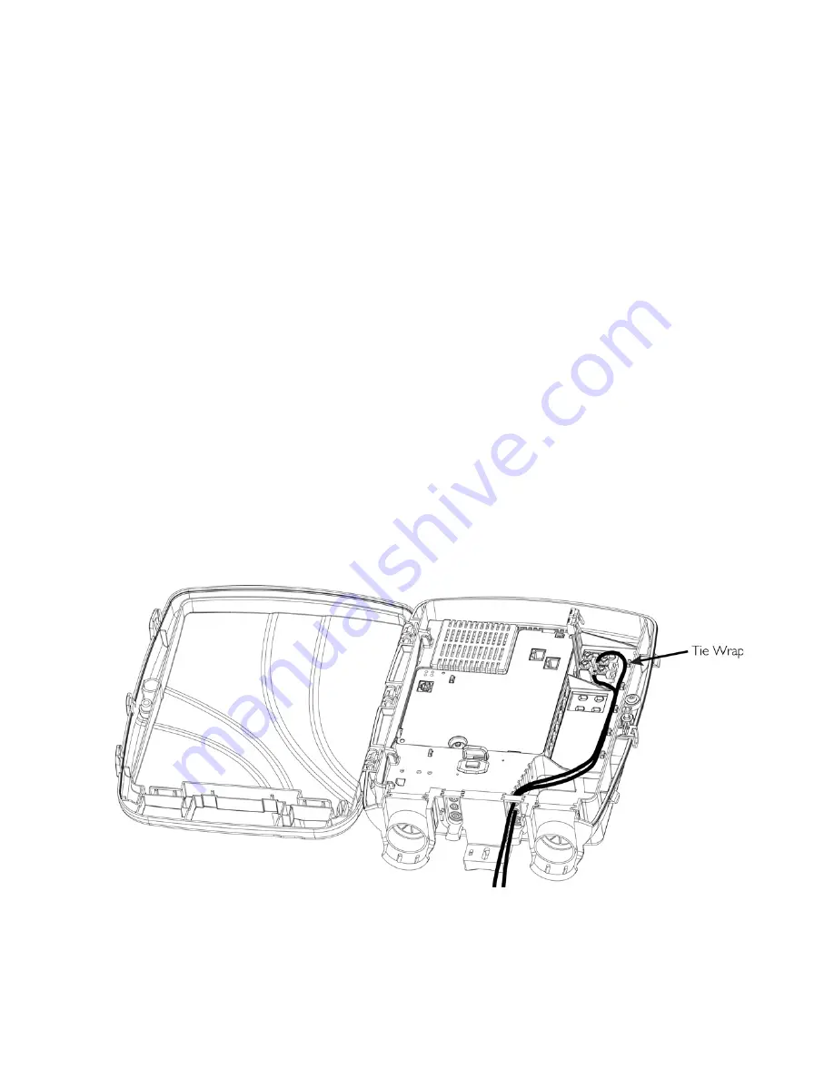
Connect the Telephone Wires
To connect the telephone wires, perform the following procedure:
1.
Insert the RJ11 terminal bridges into the electronics unit, as shown in Figure 11.
2.
Remove the grommet from slot 3 of the wire entrances.
3.
Punch a small hole in the center of the entrance circle using a pencil point.
4.
Feed the telephone wire(s) through the entrance hole, and attach the wire to the RJ-11 terminal bridge.
5.
Secure the wires with a wire tie, then trim the wire tie.
6.
Reinsert the grommet, and then seal the grommet with tape and silicone sealant.
7.
Plug the RJ11 connectors into the “TEL” ports of the electronics unit.
Primary Protector Requirements (POTS Line)
For indoor or outdoor installations, if the customer has a POTS line that is run in an aerial fashion outside the
home for any distance, or if the POTS line is run on the exterior of the building for greater than 20 feet, the
service provider must install a primary protector on the POTS line before it is connected to the iMG. The
primary protector must be installed in a “service personnel only” enclosure to ensure the end customer is
not exposed to hazardous voltages. The primary protector must be installed per manufacturer guidelines and
all local codes.
Figure 11: Connecting the Telephone Wires


