background image


4.5 Fitting the grass bag 

1) Lift the flap and pass it through the grass bag handle 
2) Fit the grass bag by lowering the frame into the slots on the mower 


DO NOT operate with out the grass bag fitted or the 

optional “cut and drop 

shoot” in place 


Содержание UPLIFT86

Страница 1: ...2018 English version Original instructions Allett Ltd Regal House Airfield Industrial Estate Hixon Stafford ST18 0PF United Kingdom Tel 44 0 1889 271503 Fax 44 0 1889 271321 For Allett spare parts Tel 44 0 1889 272095 Fax 44 0 1889 271321 Sales allett co uk www allett co uk ...

Страница 2: ...2 READ THIS MANUAL BEFORE USING AN ALLETT UPLIFT86 ROTARY MOWER YOUR SAFETY IS INVOLVED IT IS ESSENTIAL THAT OPERATORS STUDY THIS DOCUMENT FOR THEIR OWN SAFETY ...

Страница 3: ...7 2 Adjusting the blade brake clutch cable 7 3 Checking the engine oil 7 4 General engine maintenance 7 5 Fuel 7 6 Grease points 7 7 Checking blade condition 7 8 Blade removal 7 9 Blade fitting 7 10 Blade sharpening 7 11 Tensioning the blade brake clutch belt 7 12 Tensioning the Spindle timing belt 7 13 Timing the blades 7 14 Adjusting the final drive chain tension 7 15 Adjusting the rear roller s...

Страница 4: ... the intended use The way in which the Uplift86 mower is operated and maintained will have a profound effect on its performance and reliability A Uplift86 mower should be operated serviced and repaired only by persons who are familiar with its particular characteristics and who are familiar with the relevant safety procedures The safety precautions outlined in this manual and all other generally r...

Страница 5: ...n of flying objects to bystanders Keep bystanders a safe distance away from the machine Guaranteed Sound power level emitted by the mower Fast engine speed Slow engine speed Refer to operator s manual for information Engine STOP position Park brake Height of cut adjustment Clockwise rotation to cut higher Anticlockwise rotation to cut lower Height of cut in mm 25mm 1 5 speed transmission and Neutr...

Страница 6: ...eating any source of ignition until petrol vapours have dissipated Replace the fuel tank and container caps securely Replace faulty silencers Do not operate the engine in a confined space where dangerous carbon monoxide fumes can collect Before using always visually inspect to see that the cutting blades are not worn or damaged Mow only in daylight or in good artificial light Avoid operating the l...

Страница 7: ...clusion of mowing Keep all nuts bolts and screws tight to be sure that the lawnmower is in safe working condition Never store the lawnmower with petrol in the tank inside a building where fumes may reach an open flame or spark Allow the engine to cool before storing in any enclosure To reduce the fire hazard keep the engine silencer and fuel storage area free of grass leaves or excessive grease Ch...

Страница 8: ...ch side by hand 4 3 Unfold the lower handle bar 1 Use 2 x 13mm spanners to undo both the lower M8 Nyloc nuts 2 Move the lower handle bar into a comfortable position for the operator 3 Secure the M8 fasteners in the appropriate hole tighen to approx 30Nm 4 4 Attaching the cable clips Make sure all cables are securely fastened to the handlebars using the cable clips provided 1 2 3 x4 ...

Страница 9: ...ss bag 1 Lift the flap and pass it through the grass bag handle 2 Fit the grass bag by lowering the frame into the slots on the mower DO NOT operate with out the grass bag fitted or the optional cut and drop shoot in place ...

Страница 10: ...cator clamp 3 Blade engagement lever 13 Scraper prop 4 Land roll engagement lever 14 Gear lever 5 Flap 15 Cable adjuster Land drive clutch 6 Spark plug 16 Rear roller scraper 7 Starter grip 17 Height of cut adjuster 8 Oil dipstick filler cap 18 Park brake 9 Fuel filler cap 19 Grass bag 10 Air filter 1 2 3 4 5 11 13 14 15 16 17 18 19 12 6 7 9 8 10 ...

Страница 11: ...ceed as follows Engage the Park brake by pulling the lever and latching it in place DO NOT hold the blade engagement land roll or safety lever Make sure the blade engagement lever is in the furthest forward position and the blades are not engaged otherwise the engine will not start Select Neutral N with the gear lever Position the throttle in the Hare position Firmly hold the starter cord handle P...

Страница 12: ...s Disengage the red blade engagement lever to stop the blades Release the land drive lever to stop the forward travel Move the throttle lever to the furthest back position this will STOP the engine Engage the Park brake by pulling the lever and latching it in place ...

Страница 13: ... the cut height Turn the hand wheels Clockwise to cut higher Anticlockwise to cut lower Loosen the lower adjuster lock on both sides Briefly tilt the mower back and return it to the ground again to check the indicators read the same Tighten the adjuster lock on both sides Release Front adjuster clamp locks on both sides Lock front adjuster clamps on both sides ...

Страница 14: ...ive When transporting the mower between work areas it is only necessary to engage the forward drive only Proceed as follows Lift the safety operator presence lever to the handle bar and continue to hold it all the time whilst mowing Pull back the blade engagement lever so that it locks over centre Before moving forward wait for 3 seconds to allow the blades to reach full speed Note Releasing the s...

Страница 15: ... and worn or damaged components Check that covers and guards are undamaged and correctly fitted this should also include the grass bag Carry out necessary maintenance or repairs before use Clean the exterior of the machine thoroughly using a soft brush and cloth Remove all debris especially from the air filter and engine fins If the mower should happen to fail despite the care taken in manufacture...

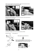
Страница 16: ...pplied to the clutch Incorrect adjustments will result in damage to the machine If the collection performance drops or the blades are slow to engage first check the load applied to the clutch The blade brake clutch has been marked to show the position of the activation lever when the correct load is applied To check the clutch load proceed as follows Make the mower safe then tilt it back to view t...

Страница 17: ...e screw head is in the brake zone as shown below If necessary to apply more force to the clutch proceed as follows Tools required 17mm spanner x 2 Using a spanner loosen the lock nut Move the adjuster DOWN in the direction shown Make adjustments in small increments until the screw head is aligned with the run mark on the clutch Brake Zone Brake Run 23kg 50Lbs pull from spring run mark Brake ...

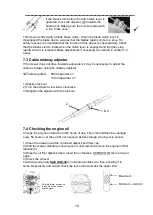
Страница 18: ... adjuster with the lock nut 7 4 Checking the engine oil Change the engine oil after the first 5 hours of use The oil should then be changed every 50 hours or at the end of each season before storage whichever is sooner 1 Clean the area around the combined dipstick and filler cap 2 With the mower standing on level ground unscrew and remove the engine oil filler dipstick 8 3 Wipe the oil filler dips...

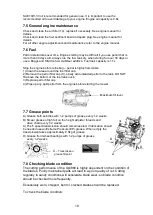
Страница 19: ...ed petrol to the tank DO NOT fill above the bottom of the fuel tank neck 3 Replace petrol filler cap 4 Wipe up any spilt petrol from the engine before starting the mower 7 7 Grease points A Grease both spindles with 1 2 pumps of grease every 1 2 weeks B Smear grease or light oil on the height adjuster threads and drive chain every 1 2 weeks C The 5 speed transmission should remain sealed if lubric...

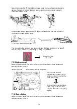
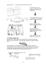
Страница 20: ... for sharpening or fitting a new blade 7 9 Blade removal Make the Mower SAFE then tilt the mower to gain better access to the blades and securely chock it in place Tools required 19mm A F socket and Torque bar 7 10 Blade fitting Make the mower SAFE then tilt the mower to gain better access to the blades and securely chock it in place Remove only the central blade screw using a 19mm socket keep the...

Страница 21: ...lade falls below the horizontal this side needs more material to be taken off Refit the central flat washer spring washer and M12 Screw Clean the blade mounting surfaces Fit the blade over the central boss and the two cap head screws Place a block of wood approximately 250mm 10 in length as shown to prevent the blade from turning Tighten the central screw to 90Nm using a torque wrench Fit the blad...

Страница 22: ... the 3 deck guard fasteners and remove the guard Using an Allen key loosen the cap head bolt on the adjuster x3 Using the 35mm spanner turn the adjuster Clockwise to tension the belt Lock the adjustment securely with the cap head bolt 30Nm torque As a guide the deflection on a correctly tensioned belt should be approximately 10mm when a 5 6kg load is applied Replace belt guard 10mm ...

Страница 23: ...t and ratchet loosen the 4 fasteners securing the idler bracket to the deck and a spanner to loosen the adjuster screw lock nut x4 IMPORTANT Before tensioning check the blade timing This is important to avoid blade collisions The blades should be timed as shown Using a spanner turn the adjuster screw clockwise to tension the belt As a guide the deflection on a correctly tensioned belt should be ap...

Страница 24: ...steners securing the idler bracket to the deck and a spanner to loosen the adjuster screw lock nut Push the idler bracket towards the spindle as far as it will go You may need to loosen the adjuster screw further This will provide sufficient slack to rotate one spindle Push Slack With the timing belt slack rotate one spindle only so that the blades line up as shown Carefully tension the timing bel...

Страница 25: ... proceed as follows Tools required 10mm spanner x2 7 17 Engine stop adjustment For the engine to stop the throttle arm must make contact with the stop switch If adjustments are necessary make the mower SAFE then proceed as follows Tools required 8mm spanner Using a pair of spanners loosen the rear roller scraper fasteners Then move the scraper nearer or further from the roller Should the scraper n...

Страница 26: ...ing and replacement Avoid washing the grass bag with high pressure water or steam cleaners A blocked mesh will prevent a clean collection and is best cleaned with a stiff bristled brush Replace a torn or damaged grass bag immediately 7 20 Inspection of safety critical components The below parts are critical to the safe operation of your lawnmower before each use check that When the park brake is e...

Страница 27: ...condition Guards in place Cutting blades Fasteners Chain and belt tension Spark plug Tire pressures Clean Debris grass from mower Engine cooling fins Fuel sediment bowl Air filter elements Inside guards Test Parking brake Engine stopping Drive engagement disengagement Replace Engine oil Spark plug Air filter elements ...

Страница 28: ...ing the mower to cut longer grass than intended or mowing on unsuitable surfaces will result in higher levels of vibration and wear 9 0 Noise reduction Best practices for reducing noise emission Forcing the mower to cut longer grass than intended or setting it to work at great depths may cause higher levels of noise emission Fitting non standard Allett blades may increase noise emission too Damage...

Страница 29: ...y Basic concepts general principles for design Basic terminology methodology EN ISO 12100 2 2003 A1 2009 Safety of machinery Basic concepts general principles for design Technical principles BS EN ISO 5395 1 2 2013 Garden equipment Powered lawnmowers Safety Measured Sound Power Level 2000 14 EC BS EN ISO 5395 1 Annex F 98dB LWA Guaranteed Sound Power Level 2000 14 EC 100dB LWA Uncertainty K 1 6dB ...

Страница 30: ... Adjust roller scraper Blocked deck chute Remove blockage Tight turns being made roller litters Avoid cutting adjacent stripes Engine speed too low Adjust engine speed to maximum Grassbag full or fabric mesh blocked Empty bag or clean fabric mesh Excessive blade wear Excessively abrasive ground conditions Increase height of cut Blade regularly makes contact with the ground Increase height of cut W...

Страница 31: ...gement Handle mounted lever engaging V belt via cable Blade engagement 2 operation handle mounted lever operating a blade brake clutch Rear roller 190mm diameter 7 5 full width and serviceable seam welded 3 piece steel roller with glass filled nylon spur gear differential Complete with adjustable scraper bar Front wheels 200mm diameter 8 0 solid tires running on twin bronze bushes Greasable Shafts...

Страница 32: ... has been undertaken by anyone other than an Allett approved service agent The fault is due to maladjustment abuse neglect or accidental damage The fault is due to lack of lubrication or maintenance The failure is due to normal wear The following parts are considered as wearing parts Their life is dependent on regular servicing and they are not therefore normally considered by the guarantee Blades...

Страница 33: ...33 14 0 Parts section UPLIFT86 ...

Страница 34: ...34 UPLIFT86 Parts Section GRASS COLLECTION MAINFRAME ASSY SPINDLE BLADE DRIVE ASSEMBLY REAR ROLLER ASSEMBLY FRONT BRUSH OPTIONAL EXTRAS FRONT WHEEL ASSEMBLY REAR ROLLER DRIVE TOP HANDLE ASSEMBLY ...

Страница 35: ...35 MODEL UPLIFT86 Mainframe Assembly Fig 1 ...

Страница 36: ...ANDWHEEL ASSEMBLY F016J10515 2 19 HOC ADJUSTMENT DECAL F016J10627 2 20 HOC STIFFNER ASSEMBLY F016J10665 2 21 ENGINE PILLAR BRACKET F016J11469 1 22 WASHER M8 FORM G WM8G 2 23 SPACER F016A57748 2 24 M8x30 BUTTON HEAD SKT SET SCREW M830BHSS 2 25 GEARBOX DECAL F016J10628 1 26 BELT COVER GEAR LEVER F016J10609 1 27 BELT COVER F016J10529 1 28 DECAL ALLETT MEDIUM AM81621 1 29 L H PIVOT BUSH F016A57676 2 3...

Страница 37: ...K MOUNTING F016J10991 1 58 REAR ROLLER BEARING F016L61256 2 60 DECK WELDED ASSY F016J11567 1 61 UPLIFT SERIAL PLATE F016J10634 1 62 ROLLER ARM PIVOT BOLT F016J10568 2 63 HOC DECK BRACKET LH FAB F016J11515 1 64 HOC DECK BRACKET RH FAB F016J11520 1 65 WHEEL ARM RH FAB F016J11530 1 66 WHEEL ARM LH FAB F016J11525 1 67 FRONT WHEEL BRACE BAR F016J11533 1 68 FRONT WHEEL PIVOT SHAFT F016J11532 1 69 BEARIN...

Страница 38: ...38 MODEL UPLIFT86 Roller Drive Assembly Fig 2 63 ...

Страница 39: ... F016J10638 7 16 UNF X 4 5 BOLT 1 18 F016J11438 TRANSMISSION BELT BRACKET B 1 19 F016J11471 7 16 SERRATED WASHER 1 20 F016J10557 CB260 BLADE BRAKE CLUTCH 1 21 F016J10587 ENGINE MOUNTING PLATE 3 22 F016J10551 BRIGGS STRATTON 950 VERTICAL 1 23 F016J10642 CABLE ANCHOR 1 24 F016J10577 ROTARY REAR ROLLER CABLE 1 25 F016J10979 DOUBLE IDLER RETURN SPRING 2 26 F016L66172 CONNECTOR 1 27 F016J10994 JOCKEY A...

Страница 40: ...F016J11504 SLOTTED CLUTCH SPACER 1 50 F016J10993 BELT GUIDE 1 51 SM616 SET SCREW M6 x 16 1 52 F016J10998 SPRING BRACKET 1 53 WM12A M12 WASHER FORM A 1 54 F016J11437 TRANSMISSION BELT BRACKET A 1 55 F016J11509 10mm P CLIP 1 56 F016J11508 M6 x 20 ROOFING BOLT 1 57 F016J11022 M6 SOCKET DOME HEAD FLANGE SCREW 2 58 WM6C WASHER M6 FORM C 1 59 F016J10535 REAR ROLLER ARM FAB RH 1 60 F016J11485 TENSIONER A...

Страница 41: ... SOCKET HD MACHINED F016J10670 4 2 10 HARDENED WASHER M12 W2 M12 6 3 FLAT WASHER M12 WM12 4 4 SET SCREW M12 x 25 SM1225 2 5 M8X25 CUP SQ BOLT CSM825 3 6 WASHER M6 FORM C WM6C 8 7 SPRING WASHER M6 SWM6 8 8 SET SCREW M6 x 25 SM625 8 9 GREASE NIPPLE M6 GNM6 2 10 2 HARDENED WASHER M12 W2 M12 6 11 NUT M12 NYLOC NNM12 2 12 M8 FLAT WAHSER FORM C WM8C 6 ...

Страница 42: ...F016J11342 1 29 ENGINE TO BLADE BELT TENSIONER FAB F016J11345 1 30 30 TOOTH PULLEY C W TAPERLOCK F016J10491 2 31 SPINDLE HOUSING F016J10498 2 32 TIMING BELT TENSIONER FAB F016J10955 1 33 SPACER 25mm F016J10494 1 34 DOUBLE TIMING BELT F016J10496 1 35 ENGINE TO BLADE BELT F016J11463 1 36 IDLER PULLEY F016J10492 2 37 IDLER PULLEY SPACER F016J10511 2 38 BALL BEARING F016J11013 4 39 SPINDLE SHAFT F016J...

Страница 43: ...43 MODEL UPLIFT86 Rear Roller Assembly Fig 4 ...

Страница 44: ... DIFFERENTIAL GEAR COVER F016Z20532 2 14 COVER PLATE F016L12499 2 15 FELT WASHER F016L12500 2 16 BLANKING PLUG F016T48526 2 17 DIFF GEAR WHEEL F016L12502 2 18 DIFFERENTIAL SHAFT F016L12550 2 19 DIFFERENTIAL PINION F016L12551 2 20 DIFFERENTIAL PINION DOUBLE F016L13870 1 21 BUSH F016L12422 3 22 SPLIT PIN F016L12399 4 23 DISTANCE TUBE F016L12552 1 24 PINION COUPLING TUBE F016L66171 1 25 LOCKING WASHE...

Страница 45: ...ITEM NO DESCRIPTION PART NUMBER USED 1 TANK SUPPORT BAR F016A75286 2 2 WING NUT F016L66135 2 3 SET SCREW M6 x 20 SM620 2 4 TOP HANDLE LOOP F016J11572 1 5 THROTTLE HANDLE PLATE F016A75800 1 6 ADAPTOR TO HANDLE F016A75817 1 7 CROSS TUBE F016J11577 1 8 ADAPTOR TUBE TO THROTTLE F016A75816 1 ...

Страница 46: ...ALL 201x30 DECAL CURVED AM81639 1 26 M5 NYLOC NUT F016L59926 4 27 M2 SCREW F016J10667 4 28 BLADE CLUTCH BACK PLATE FAB F016J11465 1 29 BLADE CLUTCH LEVER FAB F016J11460 1 30 NYLOC NUT M8 NNM8 4 31 CLUTCH LEVER PIVOT BOSS F016J10658 1 32 HD BLADE CLUTCH STOP F016J11467 1 33 M6 x 12 CAP HEAD SCM612 2 34 NUT M6 NYLOC NNM6 2 35 ORDER ITEM 44 F016J10655 36 M2 NUT F016J10668 8 37 HANDLE LEG CLAMP TAPPED...

Страница 47: ...FT F016J10608 1 2 3 4 STARLOCK WASHER F016J10287 1 3 WASHER 20mm F016A58577 1 4 NUT M12 NYLOC NNM12 1 5 M12 WASHER FORM A M12 WASHER 1 6 SOLID 200mm TYRED WHEEL F016J11574 1 7 OILITE BRONZE BUSH 1 X 3 4 X 3 4 F016J10611 2 8 GREASE NIPPLE M6 GNM6 2 6 7 FITTED BUSHED WHEEL ASSEM F016J11575 1 COMPLETE ASSEMBLY WHEEL SHAFT ASSEMBLY F016J11576 1 ...

Страница 48: ... MODEL UPLIFT86 Grass Collector Assembly Fig 7 MODEL UPLIFT86 Grass Collector Assembly Fig 7 ITEM NO DESCRIPTION PART NUMBER USED 1 GRASS COLLECTION FRAME F016J10472 1 2 GRASS COLLECTION BAG F016J10471 1 ...

Страница 49: ...ER F016J11590 MODEL UPLIFT86 Brush Assembly Fig 8 ITEM NO DESCRIPTION PART NUMBER USED 1 SOFT STIFFNESS BRUSH MEDIUM STIFFNESS BRUSH HARD STIFFNESS BRUSH F016J10436 F016J10458 F016J10445 1 2 NUT M6 NYLOC NNM6 5 3 BRUSH RETAINER STRIP F016J10449 1 4 FRONT BRUSH BRACKET FAB F016J10635 1 5 M8 x 25 CUP SQ BOLT CSM825 2 6 M8 FLAT WAHSER FORM C WM8C 2 7 NUT M8 NYLOC NNM8 2 8 M6 FLAT WASHER WM6A 10 ...

Страница 50: ...50 9 SET SCREW M6 x 30 SM630 5 15 0 Wiring schematic Notes Red Green Black OPC Operator presence control ...

Отзывы: