background image

4.5 - Model 61-T Tow Cart Assembly,   

Parts List

ITEM

PART #

DESCRIPTION

QTY

-

221056

Assembly, Power Sprayer Tow Cart (Three Pneumatic Tires)

-

1

221060

Frame, Barrel Base Sprayer

1

2

022220

Frame, Tow Model Sprayer Rear

1

3

020964

Frame, Tow Model Sprayer Front

1

4

016174

Yoke, Tow Model Sprayer Wheel

1

5

221058

Wheel and Tire Assembly

3

6

011163

Axle, Rear

1

7

011195

Axle, Front

1

8

010087

Fastener, Flat Washer, 3/4”

6

9

010972

Key, Cotter, 3/16” x 1-1/2”

6

10

010042

Fastener, Bolt, 3/8”-16 x 1-1/2”

1

11

010083

Fastener, Flat Washer, 3/8”

3

12

010102

Fastener, Hex Nut, 3/8”-16NC

1

13

012612

Fastener, Nut, 5/16”-18 Nylock

1

14

010024

Fastener, Bolt, 5/16”-18 x 2”

1

15

011175

Latch, Barrel Frame

1

16

012361

Key, Cotter, 1/8” x 1”

2

17

011752

Spring, Latch Pin

1

18

022221

Pin, Latch Barrel Frame

1

19

010082

Fastener, Flat Washer, 5/16”

1

20

011755

Shaft, Tow Handle Connecting

1

21

018483

Fastener, Bolt, 3/4”-10 x 2-1/4”

1

22

012710

Race, Bearing Thrust

4

23

100340

Bearing, Thrust NTA-1220

2

24

011584

Fastener, Nut, 3/4”-10 Nylock

1

25

221062

Handle, Tow Model Sprayer

1

26

010232

Bushing, 3\4” X 2”, Hex Red Galvanized 

(NOT SHOWN)

1

27

010259

Fitting, Elbow, 3\4”,  90°,  Street, Galvanized 

(NOT SHOWN)

1

SECTION 4

PARTS

038479

Page 45

Содержание 6500

Страница 1: ...OPERATIONS PARTS MANUAL CURING COMPOUND SPRAYERS MANUAL PART 038479 I REVISON B Note The Push Pull Carts are sold seperatly Barrel not included ...

Страница 2: ...This manual or a copy of it must be kept with the machine at all times There is a manual storage container located on the machine for your convenience ...

Страница 3: ... 7560XL 100 HOSE 300 PSI 033692 SPRAYER 7560XL 3 Piece Wand 50 HOSE 300 PSI 033692 100 SPRAYER 7560XL 3 Piece Wand 100 HOSE 300 PSI 039069 SPRAYER 9910 5 5 KA KAWASAKI 040197 SPRAYER 9910 50 HOSE 300 PSI HONDA 040198 SPRAYER 9910 100 HOSE 300 PSI HONDA 040199 SPRAYER 9910 3 Piece Wand 50 HOSE 300 PSI HONDA 040200 SPRAYER 9910 3 Piece Wand 100 HOSE 300 PSI HONDA Curing Compound Sprayers 038479 Page...

Страница 4: ...hine Dimensional Specifications 13 Engine Specifications 14 CE Deceleration of Conformity 1 0 Safety 17 State Regulations 18 Federal Regulations 19 1 1 General Safety Precautions 20 1 2 Spark Arrestor Notice 21 1 3 General Safety 22 1 4 Engine Safety 25 1 5 Operating Safety 26 2 0 Operations 29 2 1 Sprayer Assembly 28 2 2 Diaphragm Pump Operation and Maintenance 30 3 0 Service 31 3 1 Periodic Main...

Страница 5: ... Cart Assembly 42 4 5 Model 61 T Tow Cart Assembly 44 4 6 Model 6500 Pump Assembly 46 4 7 Model 7560 7560XL Pump Assembly 48 4 8 Model 9910 Pump Assembly 50 4 9 Model 9910 Pump Gearbox 53 4 10 Model 9910 Pump Control Kit 54 4 11 3 Piece Wand Assembly 55 4 12 Spray Wand Assembly 54 4 13 Decals 7560XL 58 4 14 Decals 9910 59 4 15 Decals Tow Push Cart 60 Revision Detail 62 Copyright Information 63 038...

Страница 6: ... product alterations or repairs made to the product without the written approval of Allen Allen specifically excludes from warranty any damage to any trowels resulting from an impact to the rotors 8 Impact damage to gear boxes is not covered under the Allen warranty and is deemed customer abuse 9 Allen will pay shop labor on warranty items at the Allen Shop Labor Rate in existence on the date of t...

Страница 7: ...lowing sections Complete any warranty requirements as specified by the engine manufacturer in their instructions found inside the manual box located on the back of the riding trowel operator s seat Your engine and clutch is not manufactured by Allen Engineering Corporation Inc and therefore is not covered under Allen Engineering Corporation Inc warranty Your engine manufacturer should be contacted...

Страница 8: ..._______________________________ Address _________________________________________________________________ City ____________________________________ State ________ Zip _____________ Salesman _______________________________ Mobile Phone __________________ Additional Comments _____________________________________________________ ________________________________________________________________________...

Страница 9: ...ption and part number from the PARTS section of this manual 3 Specify exact shipping instructions including the preferred routing and complete destination address 4 DO NOT return parts to AEC without receiving written authorization from AEC All authorized returns must be shipped pre paid 5 When placing an order please contact the AEC dealer nearest you Ordering Parts ALL INFORMATION SPECIFICATIONS...

Страница 10: ...ers of the Model Number and Serial Number codes Serial Number The serial number found on the identification plate is a ten digit format The model number identifies your machine and will ensure that you receive the correct replacement parts 123456 Production Sequence Model Number Serial Number Codes Model Number 6500 w 25 Hose 7560 w 25 Hose 7560XL w 25 Hose 9910 w 25 Hose HOSE LENGTH OPTIONAL HIGH...

Страница 11: ...igure 1 for serial number and model number location This plate should not be removed at any time Please record the information found on this plate below so it will be available should the identification plate become lost or damaged When ordering parts or requesting service information you will ALWAYS be asked to specify the model and serial numbers of the machine FILL IN FOR FUTURE REFERENCE Figur...

Страница 12: ...pm 27L 15 gpm 56L Max Pressure 300 psi 20 7 B 300 psi 20 7 B 300 psi 20 7 B 300 psi 20 7 B Max RPM 600 RPM 600 RPM 600 RPM 600 RPM Continuous Operation 100 psi 6 9 B 100 psi 6 9 B 100 psi 6 9 B 100 psi 6 9 B Intermittent Operation 300 psi 20 7 B 300 psi 20 7 B 300 psi 20 7 B 300 psi 20 7 B Weight 80 lb 36 29 kg 111 lb 50 35 kg 111 lb 50 35 kg 125 lb 56 7 kg ENGINE OPTIONS 6500 7560 7560XL 9910 4 0...

Страница 13: ...m 7560 16 5 8 42 23 cm 7560XL 16 5 8 42 23 cm 9910 17 7 8 45 41 cm 6500 24 1 2 62 23 cm 7560 24 1 2 62 23 cm 7560XL 24 1 2 62 23 cm 9910 24 1 2 62 23 cm 6500 12 3 4 32 25 cm 7560 16 1 2 41 91 cm 7560XL 16 1 2 41 91 cm 9910 16 1 2 41 91 cm 038479 Page 13 ...

Страница 14: ...RPM 5 4 Bore x Stroke mm 60 X 42 Compression Ratio 8 5 1 Starter Recoil Dry Weight lbs kg 29 0 13 0 Length inches 11 7 Width inches 13 6 Height inches 13 0 Fuel Capacity US Gallons ltrs 2 1 2 0 Lube Type SAE 10W 30 40 20W 40 50 Oil Capacity US Quarts ltrs 0 59 0 56 Air Cleaner Dual Element Muffler type Standard Ignition System Transistorized Magneto Lube System Splash Emission Rating EPA Carb Colo...

Страница 15: ...2500 RPM 7 6 Bore x Stroke mm 68 X 45 Compression Ratio 9 0 1 Starter Recoil Dry Weight lbs kg 33 0 15 1 Length inches 12 2 Width inches 14 3 Height inches 13 6 Fuel Capacity US Gallons ltrs 3 3 3 1 Lube Type SAE 10W 30 40 20W 40 50 Oil Capacity US Quarts ltrs 0 61 0 58 Air Cleaner Dual Element Muffler type Standard Ignition System Transistorized Magneto Lube System Splash Emission Rating EPA Carb...

Страница 16: ...t lb 2500 RPM 8 12 Bore x Stroke mm 66 0 X 50 0 Compression Ratio 8 5 1 Starter Recoil Dry Weight lbs kg 37 0 16 8 Length inches 11 8 Width inches 13 9 Height inches 14 6 Fuel Capacity US Gallons ltrs 3 6 3 4 Lube Type SAE 10W 30 Oil Capacity US Quarts ltrs 0 63 0 6 Air Cleaner Dual Element Muffler type Standard Ignition System Transistorized Magneto Lube System Splash Emission Rating EPA Carb Col...

Страница 17: ...SECTION 1 SAFETY SECTION 1 SAFETY 038479 Page 17 ...

Страница 18: ...State Regulation Proposition 65 Warming SECTION 1 SAFETY 038479 Page 18 ...

Страница 19: ...Federal Regulation Respiratory Hazard SECTION 1 SAFETY 038479 Page 19 ...

Страница 20: ...ortant information EMERGENCY is used for the identification of safety equipment first aid or emergency egress locations NOTICE used to convey safety information on labels and signs CAUTION is indicative of a potentially hazardous situation which if not avoided may result in minor or moderate injury WARNING indicates potentially hazardous situations that could result in death or serious injury DANG...

Страница 21: ... device designed to prevent the discharge of spark or flames from the engine exhaust It is often required when operating equipment on forested land to prevent the risk of fires Consult the engine distributor or local authorities and make sure that you comply with regulations regarding spark arrestors 1 2 Spark Arrestor Notice SECTION 1 SAFETY 038479 Page 21 ...

Страница 22: ... would constitute a hazard while the equipment is in operation No one other than the operator is to be in the working area when the equipment is in operation DO NOT use the equipment for any purpose other than its intended purposes or applications This equipment should only be operated by trained and qualified personnel 18 years of age and older Whenever necessary replace nameplate operation and s...

Страница 23: ...uipment in any enclosed or narrow area where free flow of the air is restricted If the air flow is restricted it will cause injury to people and property and serious damage to the equipment or engine NEVER operate the equipment in an explosive atmosphere or near combustible materials An explosion or fire could result causing severe bodily harm or even death ALWAYS keep clear of rotating or moving ...

Страница 24: ...s while starting or operating this equipment ALWAYS keep the machine in proper running condition Fix damage to machine and replace any broken parts immediately ALWAYS store equipment properly when it is not being used Equipment should be stored in a clean dry location out of the reach of children and unauthorized personnel A safety manual for operating and maintenance personnel of concrete power t...

Страница 25: ...l before servic ing equipment NEVER run engine without an air filter or with a dirty air filter Severe engine damage may occur Service air filter frequently to prevent engine malfunction NEVER tamper with the factory settings of the engine or engine governor Damage to the engine or equipment can result if operating in speed ranges above the maximum allowable ALWAYS use extreme caution when working...

Страница 26: ...s found file a claim with your carrier immediately Mark freight bill of lading as dam aged shipment 4 Do not operate High Pressure Sprayer if any guards have been removed 5 Only trained personnel should be allowed to operate your High Pressure Sprayer 6 No foreign objects such as buckets tools or materials should ever be attached to on the Sprayer during operation 7 Do not attempt to fill fuel tan...

Страница 27: ...SECTION 2 OPERATIONS SECTION 2 OPERATIONS 038479 Page 27 ...

Страница 28: ...nnector located on the 90 degree elbow below the flow control valve on the sprayer NOTE Your sprayer and components may differ from the one shown in Fig 1 This will depend on what model you order 2 1 2 Assembly of Razorback Power Sprayers to a Push Cart 1 After you uncrate all components received place the sprayer A on the push cart B Use the fasteners provided to fasten the sprayer to the frame I...

Страница 29: ...frame If you are using a 9910 sprayer place the sprayer to the front of the frame away from the barrel If you are using a 6500 7560 or a 7560XL sprayer this process will not have to be done 3 Take the reducer E and the 5 X 3 4 hose F that is supplied and fasten together Connect that end to the larger hole on the barrel Connect opposite end of suction hose to the 3 4 QDC connector located on the sp...

Страница 30: ...ct level using a high grade non detergent SAE 30 weight oil This will help prolong the pump life refer to Fig 2 3 Check the charge pressure E on the pulsation dampener before starting the pump The pressure is checked with a standard automotive air gauge The pressure should be at approximately 20 of the maximum operating pressure refer to Fig 3 4 On the pump you can adjust the pressure by clamping ...

Страница 31: ...SECTION 3 SERVICE SECTION 3 SERVICE 038479 Page 31 ...

Страница 32: ...ation Manual for additional information on engine maintenance A copy of the engine Operator s Manual was sup plied with the machine when it was shipped Check Fuel Level Daily Check Air Filter Replace as needed Daily Check and Tighten External Hardware Daily Change Engine Oil 100 hrs Replace Spark Plug 300 hrs SECTION 3 SERVICE 038479 Page 32 ...

Страница 33: ...SECTION 4 PARTS SECTION 4 PARTS 038479 Page 33 ...

Страница 34: ...d at the factory If set screw is removed or loosened for any reason re apply blue LOC TITE All grease fittings are capped with CAP PLUG GC 5 AEC PN 015692 to protect the fitting If cap becomes missing or damaged replace it as soon as possible Anti Seize is applied at the factory to all drive line coupling gear box main and counter shafts and pitch control threaded rod assemblies If these parts are...

Страница 35: ...number This manual contains an illustrated parts list for help in ordering replacement parts for your machine Follow the instructions below when ordering parts to insure prompt and accurate delivery 1 All orders for service parts include the serial number for the machine Shipment will be delayed if this information is not available 2 Include correct description and part number from the PARTS Secti...

Страница 36: ...4 1 Model 6500 Assembly Illustration SECTION 4 PARTS 038479 Page 36 ...

Страница 37: ...21035 Hose Suction Assembly 1 21 010241 Lock Barrel Mount 2 22 010189 Fitting Coupler QDC Female 1 2 1 23 040160 Fitting Nipple QDC 1 2 with male threads 1 FASTENERS 24 024669 Fastener Bolt 7 16 x 2 Barrel Lock 2 25 010092 Fastener Lock Washer 7 16 Barrel Lock 2 26 010019 Fastener Bolt 5 16 x 3 4 Shaft Guard 2 010019 Fastener Bolt 5 16 x 3 4 Pump 2 27 010036 Fastener 3 8 x 1 Pump Mount Bracket 4 2...

Страница 38: ...oupler QDC Female 3 4 1 5 010208 Bushing Reducer 3 4 X 1 2 2 6 010239 Frame 1 7 010241 Lock Barrel Mount 2 8 010242 Bracket Hose Hanger 2 9 010243 Pipe Suction 1 10 010244 Elbow 3 4 90 Female 2 11 010245 Pipe By Pass 1 12 010246 Elbow 1 2 90 Female 1 13 010259 Elbow 3 4 90 Street 1 14 010321 Tee 3 4 Female 1 15 010345 Nipple Pipe 3 4 x 3 Galvanizedanized 2 SECTION 4 PARTS 038479 Page 38 ...

Страница 39: ...51 Fastener 3 8 Hard Flat Washerat Washer Pump Mount Bracket 4 37 010026 Fastener 5 16 X 2 1 2 Engine 4 38 010082 Fastener 5 16 Flat Washerat Washer Engine 4 010082 Fastener 5 16 Flat Washerat Washer Shaft Guard 2 010082 Fastener 5 16 Flat Washerat Washer 2 Frame Guards W O Hangers 8 010082 Fastener 5 16 Flat Washerat Washer Pump 2 39 010090 Fastener 5 16 Lock Washer Engine 4 010090 Fastener 5 16 ...

Страница 40: ... Sprayer Top 1 4 039079 Frame M9910 Sprayer 1 5 033395 Engine Kawasaki 5 5 Hp 1 018961 Engine Honda 5 5 Hp 1 6 039073 Guard M9910 Sprayer End 1 7 039071 Locks Barrel M9910 2 8 010243 Suction Pipe 1 9 010244 Elbow 3 4 90 Deg Female Galvanized 1 10 039072 Bracket Isolator M9910 Sprayer 1 11 040159 Fitting Coupler QDC 1 2 W Fm Threads 1 SECTION 4 PARTS 038479 Page 40 ...

Страница 41: ...Sprayer 1 28 010189 Fitting Coupler QDC Female 1 2 1 Fastener Parts List 29 024669 Fastener 7 16 X 2 Barrel Lock 2 30 010092 Fastener 7 16 Lock Washer Barrel Lock 2 31 010023 Fastener 5 16 X 1 3 4 All Frame Guards 16 32 010022 Fastener 5 16 X 1 1 2 Engine 4 33 010082 Fastener 5 16 Flat Washer Engine 4 010082 Fastener 5 16 Flat Washer Frame Guards W O Hangers 12 010082 Fastener 5 16 Flat Washer Iso...

Страница 42: ...0242 Bracket Sprayer Hose Hanger 2 8 011163 Axle Sprayer Assembly Wheel 1 9 221058 Wheel and Tire Assembly 2 10 010087 Fastener Flat Washer 3 4 2 11 010133 Pin Cotte 3 16 x 2 2 12 010067 Fastener Bolt 1 2 13NC x 1 6 13 010106 Fastener Hex Nut 1 2 13 NC 6 14 010023 Fastener Bolt 5 16 18NC x 1 3 4 11 15 010019 Fastener Bolt 5 16 18NC x 3 4 2 16 010090 Fastener Lock Washer 5 16 21 17 010100 Fastener ...

Страница 43: ...PAGE LEFT BLANK INTENTIONALLY SECTION 4 PARTS 038479 Page 43 ...

Страница 44: ...4 5 Model 61 T Tow Cart Assembly Illustration SECTION 4 PARTS 038479 Page 44 ...

Страница 45: ...0083 Fastener Flat Washer 3 8 3 12 010102 Fastener Hex Nut 3 8 16NC 1 13 012612 Fastener Nut 5 16 18 Nylock 1 14 010024 Fastener Bolt 5 16 18 x 2 1 15 011175 Latch Barrel Frame 1 16 012361 Key Cotter 1 8 x 1 2 17 011752 Spring Latch Pin 1 18 022221 Pin Latch Barrel Frame 1 19 010082 Fastener Flat Washer 5 16 1 20 011755 Shaft Tow Handle Connecting 1 21 018483 Fastener Bolt 3 4 10 x 2 1 4 1 22 0127...

Страница 46: ...4 6 Model 6500 Pump Assembly Illustration SECTION 4 PARTS 038479 Page 46 ...

Страница 47: ...low sold as kit ONLY can not be parted 6 1002 0004 Polypropylene Roller Optional 6 1055 0004 Teflon Roller Optional 6 8 3420 0023 Base Kit Sold Separately Includes 1 Base 2 Bolts and 2 Washers 9 0100 6600C Body Cast Iron 1 0100 6600N Body Ni Resist 1 0100 6600X Body Silver Cast 1 10 2300 0023 Cover Shaft Bearing 1 11 0300 6600C Rotor Assembly Cast Iron 1 3430 0767 Rotor Assembly std Ni Resist XL 1...

Страница 48: ...4 7 Model 7560 Pump Assembly Illustration SECTION 4 PARTS 038479 Page 48 ...

Страница 49: ...oller Optional 8 1055 0004 Teflon Roller Optional 8 8 0308 7560C Rotar Assembly Cast Iron 1 3430 0745 Rotor Assembly Std Ni Resist XL 1 10 3420 0023 Base Kit Sold Separately Includes 1 Base 2 Bolts and 2 Washers 11 0104 7500C Body Cast Iron 1 0104 7500N Body Ni Resist 1 0104 7500X Body Silver Cast 1 12 2300 0022 Cover Shaft Bearing 1 13 1610 0005 Key 1 1610 0059 Key Stainless Steel 1 REPAIR KIT IT...

Страница 50: ...4 8 Model 9910 Pump Assembly Illustration 9910 D30GRGI SECTION 4 PARTS 038479 Page 50 ...

Страница 51: ...agm 2 16 9910 180150 Fastener Nut 2 181 2 3 9910 620030 O Ring 4 192 9910 1409050 Complete Valve Assembly 4 20 9910 111120 Retaining Ring 2 21 9910 620020 Cover 1 223 9910 620291 O Ring 1 23 9910 620291 Retaining Ring 1 24 9910 620190 Bearing 1 25 9910 850850 Fastener Bolt M6 x 30mm 2 26 9910 550331 Washer 2 283 9910 180101 O Ring 2 29 9910 550030 Oil Sight Glass 1 303 9910 550040 O Ring 1 31 9910...

Страница 52: ...6 0023 Drain Plug Oil 1 673 9910 740290 O Ring 1 68 9910 620930 Spacer 1 69 9910 620940 Spacer 1 70 9910 380230 Bearing 1 74 9910 390270 Fastener Nut 2 75 9910 450145 Flange 1 76 9910 110130 Fitting Hose Barb 1 2 1 4 8 Model 9910 Pump Assembly Parts List continued 9910 D30GRGI Continued From Previous Page FASTENER TORQUE REQUIREMENTS ITEM DESCRIPTION TIGHTENING TORQUE In Lbs Nm 4 Fastener Bolt M12...

Страница 53: ...M10 x 75mm 4 13 9910 1140370 Vent Plug 1 14 9910 621660 Pinion Gear 1 15 9910 320240 Retaining Ring External 2 16 9910 961780 Bearing 1 17 9910 961790 Retaining Ring Internal 1 18 9910 961800 Seal 1 19 9910 881090 Key 1 20 9910 620950 Gasket 1 4 9 Model 9910 Pump Gearbox Illustration Parts List 9910 D30GRGI FASTENER TORQUE REQUIREMENTS ITEM DESCRIPTION TIGHTENING TORQUE In Lbs Nm 2 Fastener Bolt M...

Страница 54: ...470 Pressure Release Lever 1 95 9910 320490 Locking Clip 1 96 9910 320450 Pressure Adjustment Clip 1 97 9910 320440 Threaded Guide 1 98 9910 10190 Tension Spring 1 99 9910 230120 Tension Spring Retainer 1 105 9910 620220 Relief Valve Body 1 107 9910 130171 Plug 1 109 9910 450110 Spring Holder 1 110 9910 550350 O Ring 1 111 9910 550545 Pressure Gauge Oil Filled 1 112 9910 180370 Fastener Bolt 8MA x...

Страница 55: ...7560 9910 1 6 013055 Swage 11355 6 6 Swiv 9910 ONLY 1 7 010196 Fitting Push lock 3 8 x 1 2 14 Male 6500 7560 2 8 013057 Swage 11355 8 6 Swiv 9910 ONLY 1 9 010238 Valve 3 8 Parker Ball 1 10 010188 Fitting Nipple QDC 3 8 Feale 7560 9910 1 11 028939 Hose 3 8 Aeroquip High Impulse 25 9910 ONLY 1 028939 Hose 3 8 Aeroquip High Impulse 100 Optional 1 12 013392 Hose 3 8 Push lock 25 6500 7560 1 013392 Hos...

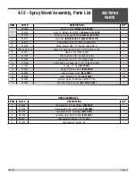
Страница 56: ...4 12 Spray Wand Assembly Illustration SECTION 4 PARTS 038479 Page 56 ...

Страница 57: ... 010196 Fitting Push Lock Male 3 8 x 1 2 14 6500 7560 1 10 010336 Coupler 1 2 Pipe 9910 ONLY 1 11 013057 Swage 11355 8 6 Perm 9910 ONLY 2 12 028939 Hose Aeroquip H I 25 9910 ONLY 25 13 028939 Hose Aeroquip H I 100 9910 ONLY 100 14 019430 Fastener Clamp 4 Mini Hose 6500 7560 1 15 032650 Nut Brass Ring Spray Gun NOT CALLED OUT 1 4 12 Spray Wand Assembly Parts List HOSE ASSEMBLIES ITEM PART DESCRIPTI...

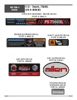
Страница 58: ... AEC INFO DECAL PART 068429 SPRAYER WARNING BRAND DECAL PART 068431 ENGINE WARNING DECAL PART 068432 SHAFT HAZARD DECAL PART 068433 AEC GLOBE DECAL PART 056341 PROPOSITION 65 WARNING DECAL PART 069225 SECTION 4 PARTS 038479 Page 58 ...

Страница 59: ... Kit 068445 AEC INFO DECAL PART 068415 ENGINE WARNING DECAL PART 068432 SPRAYER WARNINGS BRAND DECAL PART 068435 AEC GLOBE DECAL PART 068434 QTY 2 PROPOSITION 65 WARNING DECAL PART 069225 SECTION 4 PARTS 038479 Page 59 ...

Страница 60: ...4 15 Decals Tow Push Cart Kit 068425 AEC INFO DECAL PART 068426 1 CE DECAL PART 068427 SECTION 4 PARTS 038479 Page 60 ...

Страница 61: ...Notes SECTION 4 PARTS 038479 Page 61 ...

Страница 62: ...Revision Detail MANUAL REVISION DETAIL REVISION REVISION DATE REVISION REFERENCE REVISION BY 04 02 Initial Release AW A 05 17 AW B 08 18 MN 18 065 18 068 18 071 18 157 MW 038479 Page 62 ...

Страница 63: ...ny errors or inaccuracies that may appear in this man ual Allen Products are covered under one or more of the following patent numbers U S Design Patents 344 736 400 542 400 544 402 998 402 999 403 332 404 041 404 042 410 931 413 127 416 564 465 897 466 909 474 203 U S Utility Patents 5 108 220 5 238 323 5 328 295 5 352 063 5 405 216 5 476 342 5 480 257 5 480 258 5 533 831 5 562 361 5 567 075 5 61...

Страница 64: ...CONNECT WITH US ON P O BOX 819 PARAGOULD AR 72451 USA 800 643 0095 USA ONLY 870 236 7751 FAX 800 643 0097 USA ONLY 870 236 3934 WWW ALLENENG COM ...

Отзывы: