


1A
OPERATIONS
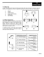
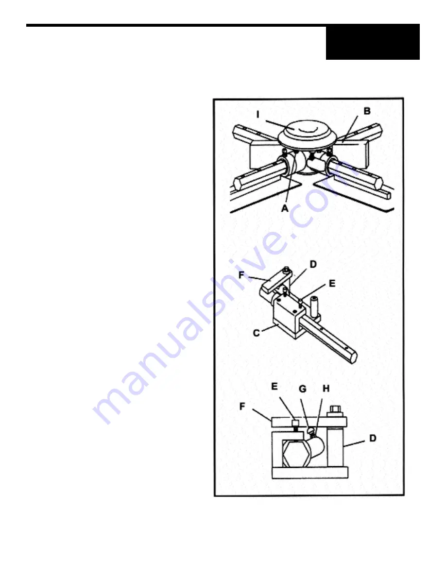
1.20 Lift Lever Adjustment
Damage to or replacement of a trowel arm can change
the adjustment of the lift lever. This can unbalance the
trowel arms and cause the trowel to wobble during
operation. To operate smoothly the lift lever on all
arms must be adjusted the same to ensure that the
trowel is balanced correctly. Adjust trowel arms using
optional trowel arm jig as described below.
NOTE: Make sure that there is no pitch in the
blades before attempting to remove a
trowel arm.
1. Block up pressure plate (I) using wooden block
(B).
2. Remove stabilizer ring from spider assembly
(only on available models).
3. Remove blades from trowel arms.
4. Loosen hex head cap screw (A) and remove it
and the external star washer from the spider
boss.
5. Remove trowel arms from spider 4-boss with
lift levers in place.
6. Clean flats on trowel arm before placing it in
the trowel arm jig (PART# 016863).
7. For PRO 1200 SD series trowels use the medium
spacer (1-1/4 X 2-1/2) (D).
8. Insert trowel arm into trowel arm jig as shown.
9. Tighten socket head bolts (E) down on the
trowel arm to hold in place.
10. Place carriage bolts (G) on lift lever under the
trowel arm jig (F) as shown.
11. Loosen jam nut (H) and adjust the carriage bolt
so that the top of the bolt is just touching the
bottom of the trowel arm jig and tighten jam nut
(H).
12. Attach and trowel arm to spider boss and blades
to arms.
13. Tighten down hex head cap screw to secure
arm in place.
14. Reattach stabilizer ring (only on available mod-
els).
1A-16
Содержание 032034
Страница 23: ...2A PARTS ENGINE MOUNT SYSTEM 2A 4 VANGUARD LINAMAR...
Страница 27: ...2A PARTS SUPER DUTY SD GEARBOX RIGHT HAND SITTING ON MACHINE SOM PART 029141 2A 8...
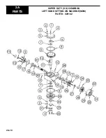
Страница 29: ...2A PARTS 2A 10 SUPER DUTY SD GEARBOX LEFT HAND SITTING ON MACHINE SOM PART 029142...
Страница 31: ...2A PARTS FUEL SYSTEM ASSEMBLY 2A 12...
Страница 33: ...2A PARTS 2A 14 ELECTRICAL COMPONENTS...
Страница 35: ...2A PARTS 2A 16 VANGUARD WIRING DIAGRAM...
Страница 37: ...2A PARTS 2A 18 PITCH CONTROL ASSEMBLY...
Страница 39: ...2A PARTS STEERING LEVER ASSEMBLY 2A 20...
Страница 41: ...2A PARTS SPRAY SYSTEM ASSEMBLY 2A 22...
Страница 43: ...2A 24 2A PARTS SPIDER ASSEMBLY...


