Allen-Bradley ControlLogix 1756-STRT3 Скачать руководство пользователя страница 75

1

1

7

7

5

5

6

6

-

-

Q

Q

S

S

1

1

0

0

4

4

A

A

-

-

E

E

N

N

-

-

P

P


C

C

o

o

n

n

t

t

r

r

o

o

l

l

L

L

o

o

g

g

i

i

x

x


Q

Q

u

u

i

i

c

c

k

k


S

S

t

t

a

a

r

r

t

t

Page 75

 Adding Ladder Logic

Add ladder logic to your program that uses the analog modules you just configured.

1. From the 

Controller Organizer

, double click on 

MainRoutine

 to open the main routine.

2. Click on the 

 icon on the toolbar to add a new rung to the routine.

3. With rung 1 highlighted, press the 

[Insert]


key on the keyboard.
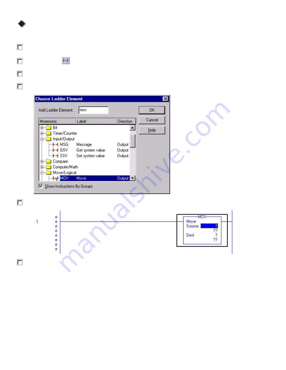
4. Type 'mov'


as shown below and click on 

OK

.

5. Verify that rung 1 appears as shown below.

6. Right click on the 

question mark (?)


in the blue area next to Source in the MOV instruction and choose

New Tag

.

Allen-Bradley Parts

Содержание ControlLogix 1756-STRT3

Страница 1: ...ControlLogix Starter Kit 1756 STRT3 Quick Start Manual Allen Bradley Parts...

Страница 2: ...the Application Installation and Maintenance of Solid State Control available from your local Allen Bradley office describes some important differences between solid state equipment and electromechan...

Страница 3: ...PROPERTIES FOR THE MAIN TASK AND THE MAIN PROGRAM ______________________19 CONFIGURING YOUR I O ____________________________________________________________22 CONFIGURING THE DISCRETE OUTPUT MODULE __...

Страница 4: ...EXPORT FILE FORMAT _________________________________________________54 IMPORTING THE CHANGED EXPORT FILE ________________________________________________54 VERIFYING YOUR CHANGES IN THE IMPORTED FILE...

Страница 5: ...______________________79 EXAMINING THE COOKIE ARRAY AND ADDING YOUR OWN COOKIE RECIPE _______________________80 REVIEWING THE LADDER PROGRAM____________________________________________________81 EXERC...

Страница 6: ...1 17 75 56 6 Q QS S1 10 04 4A A E EN N P P C Co on nt tr ro ol lL Lo og gi ix x Q Qu ui ic ck k S St ta ar rt t Page 6 Notes __________________________________________________________________________...

Страница 7: ...n when you are prompted to open one of the above files About the ControlLogix Platform The ControlLogix platform provides a modular control platform suited for sequential process drive or motion contr...

Страница 8: ...to control multiple stations in a process About the CompactLogix Platform The features scalability and small size of the CompactLogix platform provide a powerful alternative for machine level control...

Страница 9: ...ogix controller documentation set 1756 QS104A EN P ControlLogix quick start manual Document Conventions Throughout this manual we have used the following conventions to help guide you through the exer...

Страница 10: ...Linx software from the CDs that come with RSLogix 5000 programming software Install firmware onto the ControlLogix controller The installation instructions for the controller publication 1756 IN101 de...

Страница 11: ...es configure your I O modules alias the module tags to the tags you created in your ladder logic Follow the steps below to complete Exercise 1 Place a checkmark in the square next to each step as you...

Страница 12: ...In the Revision field select the highest revision number available revision 11 in the example screen shown below 3 In the Name field type Controller1 for the controller name 4 From the Chassis Type p...

Страница 13: ...olders and files that contain all of the information about the programs and data in the current controller file The default main folders in this tree are Controller File Name contains controller scope...

Страница 14: ...he right mouse button brings up many different context sensitive popup menus Often you will find that this is a shortcut to access the property window or to menu options from the menu bar Double click...

Страница 15: ...t Page 15 3 From the Controller Organizer double click on the Main Routine icon An empty rung appears in the Ladder Editor 4 From the Ladder Instructions toolbar as shown below click on the Bit tab T...

Страница 16: ...a ar rt t Page 16 5 Click on the XIC Examine On icon to enter the instruction on the rung The XIC instruction appears on the rung in the Ladder Editor as shown below 6 Right click on the Question Mark...

Страница 17: ...Type selections choose Base 9 From the Data Type menu choose BOOL 10 From the Scope selections choose MainProgram 11 Click on OK Your rung should now look like this 12 Click and hold the mouse button...

Страница 18: ...f the screen or in the Results window if it is selected under the View menu If there are errors you must correct them before the rung will verify You can also verify the entire routine by choosing Ver...

Страница 19: ...Controller Organizer right click on the MainTask icon and choose Properties The Task Properties dialog appears 2 Click on the Program Schedule tab and verify that the MainProgram appears in the Sched...

Страница 20: ...n the Configuration tab and verify that the Watchdog is set for 500 ms The Watchdog is a task scan time watchdog which if exceeded faults the processor 4 Click on OK to close the Task Properties dialo...

Страница 21: ...choose MainRoutine from the Main field pull down menu FYI Every program folder must have a main routine assigned All other routines in a program folder are only executed if they are selected as a faul...

Страница 22: ...module tags Configuring the Discrete Output Module Add the discrete output module in slot 0 of the I O Configuration list 1 From the Controller Organizer right click on the I O Configuration folder an...

Страница 23: ...ith what the user configured for that particular slot in their project The following data is read and compared Vendor Product Type Catalog Number Major Revision Minor Revision Select one of the follow...

Страница 24: ...e Controller Organizer double click on the Controller Tags icon The Data Monitor appears with 3 entries in the Tag Name column Local 0 C Local 0 I Local 0 O These entries are tag structures resulting...

Страница 25: ...ge in which tags are recognized within the routines Tags created at the controller scope are accessible to all routines in all program folders those created at the program scope are accessible only to...

Страница 26: ...of the Local 0 I tag to display all of the input tags for this module You should see 4 entries under this tag structure 4 Click on the sign in front of the Local 0 O tag to display all of the output t...

Страница 27: ...display all of the input tags for this module The Local 2 I Data tag contains all of the actual input bits like the input image data table in a PLC 5 processor Mapping I O Points to Tags Assign the ta...

Страница 28: ...of the module and use Local 2 I Data 0 as the alias tag 9 Verify your tag database appears as follows then choose Save to save your program C C Co o on n ng g gr r ra a at t tu u ul lla a at t ti iio...

Страница 29: ...gure your communications driver verify communications to the controller download your program to the controller using the driver you configured create a new periodic task create a new program create a...

Страница 30: ...expanded as indicated by the sign you can click on the sign or double click on the network or device icon to collapse the view The right pane of the RSWho display is the List Control which is a graphi...

Страница 31: ...CP3 is connected from the serial port on the front of the controller to the serial port on your PC 4 Click on the Auto Configure button If the serial cable is attached correctly RSLinx automatically s...

Страница 32: ...ix x Q Qu ui ic ck k S St ta ar rt t Page 32 Verifying Communications to the Controller Use RSWho to verify that you can communicate with the controller via the RS 232 DF1 driver you just configured...

Страница 33: ...Q QS S1 10 04 4A A E EN N P P C Co on nt tr ro ol lL Lo og gi ix x Q Qu ui ic ck k S St ta ar rt t Page 33 2 Double click on the controller icon The controller expands to display the backplane Allen B...

Страница 34: ...gix Controller Browse through the tree until you see all the devices connected to the backplane as shown below 4 Verify that the small square LED to the right of the serial cable on the controller in...

Страница 35: ...ownload button You will see the following dialog box The controller must be in Program or Remote Program mode in order to download If it is not you are prompted to change modes before downloading Depe...

Страница 36: ...ck on the Tasks icon and choose New Task The New Task dialog appears 2 In the Name field type Task2 3 In the Description field type This task is similar to an STI in a PLC 5 4 In the Type field be sur...

Страница 37: ...ram folder will execute once every 1000 milliseconds or once every second Also notice that under Program2 in the Controller Organizer there is now an item called Program Tags All program scoped tags a...

Страница 38: ...click on OK The next thing you want to do is assign a routine to be the MainRoutine for Program2 6 From the Controller Organizer right click on the Program2 icon and choose Properties The Program Prop...

Страница 39: ...n the button choose a data type of COUNTER 6 In the Dim 0 field click on the up arrow until a value of 10 is displayed and click on OK 7 Press the Enter key to accept the tag 8 Click on the sign in fr...

Страница 40: ...1 17 75 56 6 Q QS S1 10 04 4A A E EN N P P C Co on nt tr ro ol lL Lo og gi ix x Q Qu ui ic ck k S St ta ar rt t Page 40 Notes __________________________________________________________________________...

Страница 41: ...Exercise 3 Place a checkmark in the square next to each step as you complete it This will help you keep your place as you work through the steps Editing and Testing Your Routine Add ladder instructio...

Страница 42: ...040 and press Enter 8 Press Enter again to accept 0 as the Accum value The Preset and Accumulator values in ControlLogix are double integer words This allows you to enter 32 bit values 9 Press the Ins...

Страница 43: ...it is selected under the View menu If there are errors you must correct them before the rung will verify If there are no errors the e s next to the rung will change to i s this indicates the logic sti...

Страница 44: ...Value Use the trending feature of RSLogix 5000 software 1 From the Controller Organizer right click on the Trends folder and choose New Trend The New Trend dialog appears 2 In the Name field type Tre...

Страница 45: ...04 4A A E EN N P P C Co on nt tr ro ol lL Lo og gi ix x Q Qu ui ic ck k S St ta ar rt t Page 45 4 Right click on the Trend Chart window and choose Chart Properties The RSTrendX Properties dialog appe...

Страница 46: ...75 56 6 Q QS S1 10 04 4A A E EN N P P C Co on nt tr ro ol lL Lo og gi ix x Q Qu ui ic ck k S St ta ar rt t Page 46 5 Click on the Pens tab then click on Add Configure Tags The Configure Tags dialog ap...

Страница 47: ...end Chart to close Trend1 17 Save your project Testing Your Program Periodic Task Continue with the testing of the Periodic Task to see that your program does what you intended it to do Periodic Task...

Страница 48: ...constraints you can trend data elements of type BOOL SINT INT DINT and REAL you are limited to sampling eight unique data elements and you will be limited to activating data collection for one trend...

Страница 49: ...en to open the controller file Controller1 ACD that you created in Exercise 1 2 Double click on the RSLogix 5000 icon on the desktop to open another session of RSLogix 5000 3 Open the ReusableCode ACD...

Страница 50: ...tion 4 Click on OK to save your changes and close the Program Properties dialog Changing the Name of the Main Routine Change the name of MainRoutine and review the ladder diagram 1 In the ReusableCode...

Страница 51: ...choose Edit Tags The Program Tags ReusedProgram dialog appears Notice the Xs to the left of the tag names This is because the tag points to an alias that does not exist in this project You must re ma...

Страница 52: ...structions to other projects the same way we copied the Program 2 The second step we renamed the Program and the Routine This is not a required step we renamed them to emphasize their reuse 3 The thir...

Страница 53: ...the square next to each step as you complete it This will help you keep your place as you work through the steps Examining the Controller File Open the ImportExport ACD file 1 From the File menu choos...

Страница 54: ...ications path The next section deals with Modules Notice that each module configured in our controller file is listed The name identifies the module other attributes such as the catalog number and the...

Страница 55: ...ck on the sign in front of the myCounter tag to display the counter values Verify the preset has changed from 50 to 100 Importing Tags From a CSV File 1 From the Start menu choose Programs Microsoft E...

Страница 56: ...8 Click on Import 9 If it is not already open open the Data Monitor so that you can view the Controller Tags 10 Click on the Edit Tags tab to enter the edit mode Observe the new tags that were created...

Страница 57: ...eps Opening the Controller file and Saving it as a New File Open the controller file and save it under a new name 1 Open the controller file Controller1 ACD 2 Download the file to the controller in sl...

Страница 58: ...e fastest RPI configured for all owner controllers for input modules or faster than the RPI configured for the one owner controller for output modules Inhibit Module checkbox Check Uncheck this box to...

Страница 59: ...can configure many diagnostics and output states on the module down to the point level 2 Under the Output State During column from the Program Mode pull down menu for Point 0 choose On Choosing On wi...

Страница 60: ...k on OK to apply the changes to the module configuration 8 Click on the Diagnostics tab The Diagnostics screen that appears is used only in the Online mode to reset the fuses 9 Click on the Backplane...

Страница 61: ...the controller The number between the colons is the slot number of the module in this case the module is in slot 0 The characters appearing after the last colon i e the C the I and the O indicate whet...

Страница 62: ...iter between the style and the rest of the value Note that some of the configuration tags consist of 32 bits These bits are numbered from 0 to 31 from right to left The individual bits that are set in...

Страница 63: ...ic and input states on the module down to the point level 3 Verify that the Enable Change of State settings are as shown above 4 Click on the Backplane tab The Backplane screen is used only in an onli...

Страница 64: ...1 17 75 56 6 Q QS S1 10 04 4A A E EN N P P C Co on nt tr ro ol lL Lo og gi ix x Q Qu ui ic ck k S St ta ar rt t Page 64 Notes __________________________________________________________________________...

Страница 65: ...as you complete it This will help you keep your place as you work through the steps Opening the Controller file and Saving it as a New File Open the controller file and save it under a new name 1 Ope...

Страница 66: ...lL Lo og gi ix x Q Qu ui ic ck k S St ta ar rt t Page 66 4 When the next Module Properties screen appears verify the parameters below and click on Next The next Module Properties screen that appears...

Страница 67: ...oint data format To scale a module choose two points along the module s operating range and apply low and high values to those points Note In choosing two points for the low and high value of your app...

Страница 68: ...Last State Click on this button under Output State in Program Mode or Fault Mode if you want the output channel to remain at the last output value OR User Defined Value Click on this button under Outp...

Страница 69: ...Module Properties screen appears modify the parameters for Channel 0 as shown below Notice the LL and HL pointers give you a quick visual for your Clamp Limits 11 Click on Next The next Module Propert...

Страница 70: ...t ControlBus parameters 13 Click on Finish Verifying Tags Verify that the tags were created for the 1756 OF4 module in slot 3 1 From the Controller Organizer double click on the Controller Tags icon T...

Страница 71: ...log Input Module Configure the analog input module in slot 4 for this controller 1 Add a 1756 IF8 Analog Input Module to the controller s I O Configuration 2 Enter the parameters as shown below and cl...

Страница 72: ...x Q Qu ui ic ck k S St ta ar rt t Page 72 The next Module Properties screen that appears as shown below is active only in an Online mode 4 Click on Next 5 When the next Module Properties screen appear...

Страница 73: ...S St ta ar rt t Page 73 6 When the next Module Properties screen appears enter the Process Alarms for channel 0 as shown below and click on Next The next Module Properties screen that appears as show...

Страница 74: ...t ControlBus parameters 8 Click on Finish Verifying Tags Verify that the tags were created for the 1756 IF8 module in slot 4 1 If the Tag Monitor is not already open double click on Controller Tags in...

Страница 75: ...om the Controller Organizer double click on MainRoutine to open the main routine 2 Click on the icon on the toolbar to add a new rung to the routine 3 With rung 1 highlighted press the Insert key on t...

Страница 76: ...r rt t Page 76 7 Enter the parameters as shown below Important Choose Controller1 controller in the Scope field before you select the Alias For tag 8 Click on OK to create this new alias tag Rung 1 sh...

Страница 77: ...ill appear either in the status bar at the bottom of the screen or in the Results window if it is selected under the View menu If there are errors you must correct them before the rung will verify You...

Страница 78: ...1 17 75 56 6 Q QS S1 10 04 4A A E EN N P P C Co on nt tr ro ol lL Lo og gi ix x Q Qu ui ic ck k S St ta ar rt t Page 78 Notes __________________________________________________________________________...

Страница 79: ...er defined structures and arrays 1 Open the controller file UserDefined ACD 2 Click on the to the left of the Data Types folder to expand it If the folder is already expanded there will be a to the le...

Страница 80: ...t name for the Cookies tag 3 Click on the sign to the left of the Cookies 0 element The screen appears as shown below Notice that Cookies is a 3 element array of type CookieRecipe 4 Click on the Monit...

Страница 81: ...appears as shown on the previous page and below On the first rung of the program you select which type of cookie to make and the index of the Cookie Array is updated to use the correct Cookie Recipe...

Страница 82: ...he subroutine BakeCookies which makes the cookies and bakes them C C Co o on n ng g gr r ra a at t tu u ul lla a at t ti iio o on n ns s s Y Y Yo o ou u u h h ha a av v ve e e n n no o ow w w c c co o...

Страница 83: ...Logix 5000 Getting Results Guide The Adobe Acrobat Reader is launched and the pdf file for the RSLogix 5000 Getting Results Guide opens 2 See if you can find the section of the manual entitled Quick S...

Страница 84: ...ng with the software Basic information on what RSLogix 5000 is and helpful tips to help you find your way around the software Menu and command information that will help you to learn the different men...

Страница 85: ...ow some of the related words or phrases 4 For example type in the word Alarms A list of topics containing the word Alarms appears at the bottom of the Find tab Look through the list to see the types o...

Страница 86: ...1 17 75 56 6 Q QS S1 10 04 4A A E EN N P P C Co on nt tr ro ol lL Lo og gi ix x Q Qu ui ic ck k S St ta ar rt t Page 86 Notes __________________________________________________________________________...

Страница 87: ...6 Q QS S1 10 04 4A A E EN N P P C Co on nt tr ro ol lL Lo og gi ix x Q Qu ui ic ck k S St ta ar rt t Page 87 Notes __________________________________________________________________________ Allen Bra...

Страница 88: ...1 17 75 56 6 Q QS S1 10 04 4A A E EN N P P C Co on nt tr ro ol lL Lo og gi ix x Q Qu ui ic ck k S St ta ar rt t Page 88 Notes __________________________________________________________________________...

Страница 89: ...sary information is provided 1 2 3 Can we add more information to help you procedure step illustration feature example guideline other explanation definition Technical Accuracy all provided informatio...

Страница 90: ...NECESSARY IF MAILED IN THE UNITED STATES BUSINESS REPLY MAIL FIRST CLASS MAIL PERMIT NO 18235 CLEVELAND OH POSTAGE WILL BE PAID BY THE ADDRESSEE 1 ALLEN BRADLEY DR MAYFIELD HEIGHTS OH 44124 9705 PLEA...

Страница 91: ...Allen Bradley Parts...

Страница 92: ...Publication 1756 QS104A EN P October 2002 2 PN 957707 80 Copyright 2002 Rockwell Automation All rights reserved Printed in the U S A...

Отзывы: