Industrial Computers for Hazardous Locations Accessories
2
Rockwell Automation Publication 6181X-PC001C-EN-P - February 2020
Summary of Changes
This publication contains new and updated information as indicated in this table.
See
Additional Resources on page 4
for where to find this information.
Voltage Precautions
The computers contain line voltages. Disconnect all power to the computer before you install or remove
components.
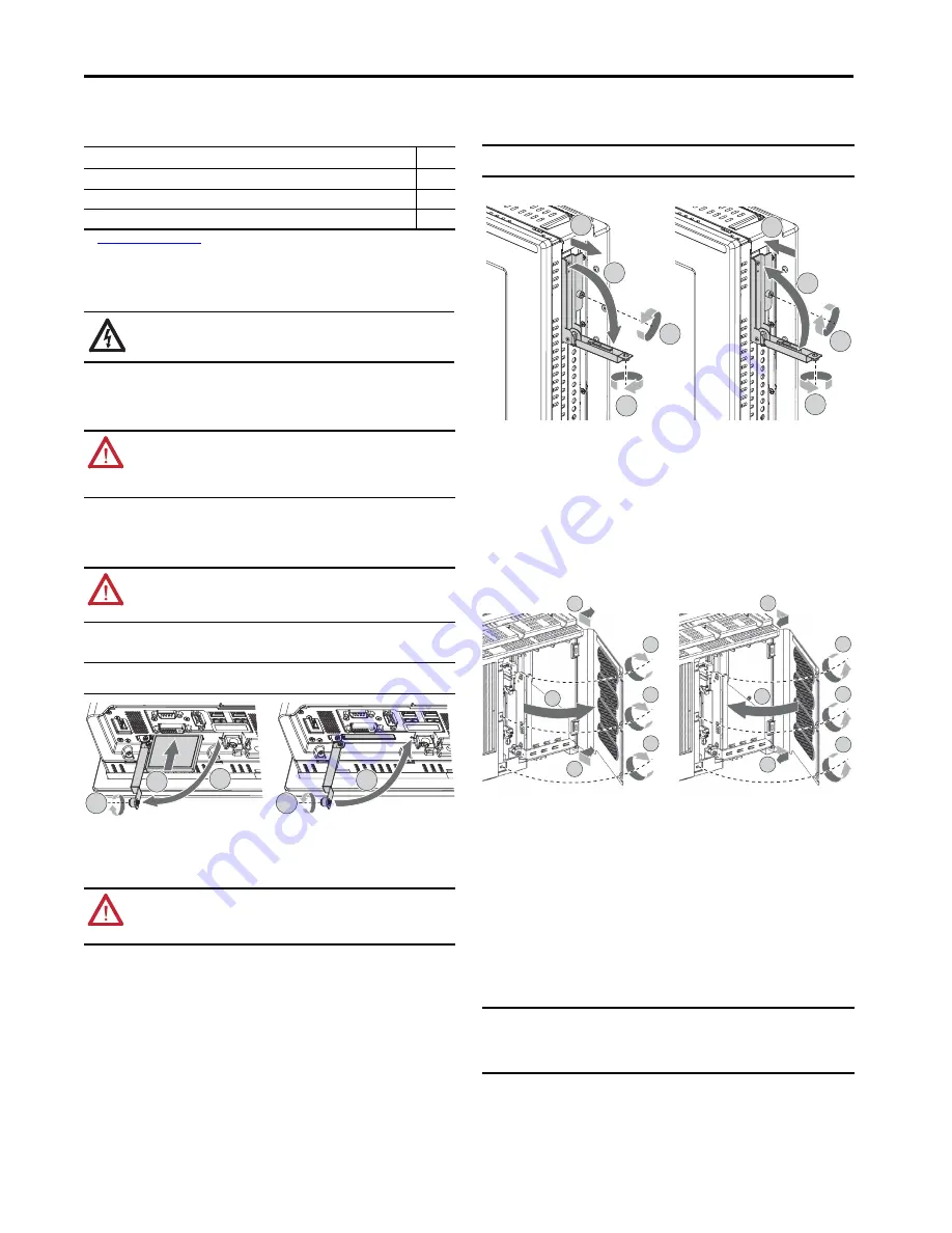
Load a CompactFlash Card
(Cat. Nos. 6189V-CFSSD8GB and 6189V-CFSSD16GB)
Follow these steps to install a CompactFlash (CF) card in the bottom CF card slot.
1. Loosen the screw that secures the CF card slot cover (A).
2. Open the CF card slot cover (B).
If necessary, remove an inserted card by pushing the button on the hinge side.
3. Insert the new CF card into the slot until it is firmly seated (C).
4. Close the CF card slot cover (D).
5. Tighten the CF card slot cover screw (E).
Replace a Solid-state Drive
(Cat. Nos. 6189X-128GBSSD and 6189X-256GBSSD)
Follow these steps to replace a solid-state drive (SSD) tray in the SSD bay on the side of the computer.
1. Loosen the screw that secures the slot cover of the drive bay (A).
2. Loosen the screw that secures the drive bay lever (battery).
3. Open the drive bay lever (C).
4. Pull out the existing SSD tray (D).
5. Push in the new SSD tray (E).
6. Close the drive bay lever (F).
7. Tighten the screw that secures the drive bay lever (G).
8. Tighten the screw that secures the slot cover of the drive bay (H).
Tools for Component Replacement
The following tools are required for component replacement:
• #2 cross-head screwdriver
• Anti-static
wriststrap
• Properly grounded tools and equipment
Remove the Rear Cover of the Computer
Follow these steps to remove the rear cover (the integrated display computer is shown).
1. Shut down the computer and all peripherals that are connected to it.
2. To avoid exposure to high energy levels, disconnect all cables from power outlets.
3. Loosen the three screws that secure the rear cover (A).
4. Open the cover (B) and detach it from the chassis (C).
Reinstall the Rear Cover of the Computer
Follow these steps to reinstall the rear cover.
1. Verify that all components are installed according to instructions.
2. Verify that no tools or loose parts are left inside the computer.
3. Reinstall any expansion boards, peripherals, and system cables that were previously removed.
4. Reattach the rear cover to the chassis (D).
5. Close the cover (E).
6. Tighten the three screws to secure the rear cover (F).
7. Reconnect all external cables and power to the computer.
8. To start the computer, press the power switch.
Computer Memory Modules
The computers have two dual-channel DDR3 SO-DIMM slots that support up to 16 GB maximum system
memory.
Topic
Page
Added the photograph and instructions for the memory modules with heatsinks.
Added the Install the PCI Riser Card section.
Added the Install the Sun Shield section.
SHOCK HAZARD:
Disconnect all power to the computer before you remove components.
Failure to disconnect power can result in severe electrical shock to an individual or electrostatic
discharge (ESD) damage to the computer and components.
WARNING:
The CF card slot on the bottom side of all computer models is hot-swappable but only
in a nonhazardous location. You can insert or remove a card from this slot while the computer is
running.
When the computer is used in a hazardous location, do not insert or remove a card in the bottom
CF card slot unless power has been switched off.
ATTENTION:
When properly seated, more than 80% of the CF card easily inserts into the slot
before you encounter resistance. If you encounter resistance sooner, then remove the card, rotate
it 180°, and reinsert.
Do not force the card into the slot or you can damage the connector pins.
IMPORTANT
For computers in ATEX and IECEx applications, the CF card slot cover screw (step E in the
illustration) must be hand-tightened and verified as secure.
WARNING:
The SSD bay on the side of all computer models is not hot-swappable. You must first
shut down the computer before you can insert or remove an SSD tray from this bay.
Do not connect or disconnect components unless power has been switched off and the area is
known to be nonhazardous.
A
B
C
E
D
IMPORTANT
For computers in ATEX and IECEx applications, both screws for the drive bay (steps G and
H in the illustration) must be hand-tightened and verified as secure.
IMPORTANT
Computer performance is optimized when both slots are populated with memory
modules of the same capacity. All 6181X computers ship with a dual memory module
configuration.
All memory module upgrades ship with heatsinks. These memory modules replace any
existing memory configurations, including modules without heatsinks.
Integrated Display Computer Shown
D
C
A
B
E
F
H
G
C
A
B
C
A
A
F
F
F
D
D
E


