background image

33

Publication 1761-UM004B-EN-P - June 2006

Appendix

 A

Specifications and Dimensions

General Specifications

AIC+ Advanced Interface Converter - 1761-NET-AIC

Environmental Specifications

Certifications

Attribute

Value

24V dc Power Source 
Requirement

20.4...28.8V dc

Current Draw

0...120 mA


200 mA inrush current, max 

Internal Isolation (see below)

500V dc

DH-485, DF1, or User Network

Number of nodes, max = 32 per multidrop network 

Length, max = 1219 m (4000 ft) per multidrop 
network 

Number of ganged multidrop networks, max = 2

Attribute

Value

Operating Ambient Temperature

0...60 °C (32...140 °F) 

Storage Temperature

-40...85 °C (-40...175 °F)

Certification

Value

Agency Certification

(1)

(1)

See the Product Certification link at http:ab.com for Declaration of Conformity, certificates, and other 
certification details.

UL 1604

C-UL C22.2 No. 213 

Class I Division 2 Groups A, B, C, D

CE compliant for all applicable 
directives

Allen-Bradley Spares

Содержание 1761-NET-AIC

Страница 1: ...AIC Advanced InterfaceConverter Catalog Number 1761 NET AIC User Manual Allen Bradley Spares...

Страница 2: ...umed by Rockwell Automation Inc with respect to use of information circuits equipment or software described in this manual Reproduction of the contents of this manual in whole or in part without writt...

Страница 3: ...s to this manual since the last printing To help you find new and updated information in this release of the manual we have included change bars as shown to the right of this paragraph Topic Page Upda...

Страница 4: ...Publication 1761 UM004B EN P June 2006 4 Summary of Changes...

Страница 5: ...anced Interface Converter 13 Wire the Power Supply 13 Wire to the Network Ports 14 Cable Choices 16 Recommended User supplied Components 19 Chapter 3 Network Connections Network Diagrams 21 Point to p...

Страница 6: ...04B EN P June 2006 ii Table of Contents Appendix A Specifications and Dimensions General Specifications 33 Hardware Handshaking 34 Auto Transmit Delay turnaround time per Communication Rate 35 Mountin...

Страница 7: ...Bradley Small Logic controllers You should have a basic understanding of SLC 500 and MicroLogix products and be able to interpret the ladder logic instructions required to control your application If...

Страница 8: ...l and use your modular SLC 500 programmable controller User Manual for Modular Hardware Style Programmable Controllers 1747 UM011 A description on how to install and use your MicroLogix 1000 programma...

Страница 9: ...ni DIN port s cable However if a MicroLogix controller is not connected to this port a 24V dc power supply connected to the converter s external power terminals is required The dc power source selecto...

Страница 10: ...unication rates Operation Modes The AIC interface converter can be used in the following modes Point to point isolator RS 232 to RS 485 isolator RS 232 to half duplex user mode ASCII isolator Communic...

Страница 11: ...tion There is no node address associated with the network port The node address is configured in the device connected with this port The node address is configured in the device connected with this po...

Страница 12: ...Publication 1761 UM004B EN P June 2006 8 Product Overview...

Страница 13: ...n a technical construction file EN 50081 2 EMC Generic Emission Standard Part 2 Industrial Environment EN 50082 2 EMC Generic Immunity Standard Part 2 Industrial Environment This product is intended f...

Страница 14: ...erate switches while circuit is live unless the area is known to be nonhazardous This product must be installed in an enclosure All cables connected to the product must remain in the enclosure or be p...

Страница 15: ...erter 1 Mount your DIN rail 2 Snap the DIN rail latch into the closed position 3 Hook the top slot over the DIN rail 4 While pressing the AIC interface converter against the rail snap the AIC interfac...

Страница 16: ...instructions to mount your AIC interface converter to a panel 1 Remove the mounting template from this document 2 Secure the template to the mounting surface 3 Drill holes through the template 4 Remov...

Страница 17: ...us locations external power is not required if the AIC interface converter 8 pin mini DIN com port is connected to a MicroLogix controller IMPORTANT Some devices provide power to the AIC interface con...

Страница 18: ...elow Single Cable Connection Multiple Cable Connection IMPORTANT A daisy chained network is recommended Other chained networks are not recommended Connector Connector Connector Belden 3106A or 9842 Be...

Страница 19: ...re Pair Connect This Wire To This Terminal Shield Drain Non jacketed Terminal 2 Shield Blue Blue Terminal 3 Common White Orange White with Orange Stripe Terminal 4 Data B Orange with White Stripe Term...

Страница 20: ...P3 Cable Cable Length Connects from to AIC Interface Converter 1747 CP3 1761 CBL AC00 3 m 9 8 ft 45 cm 17 7 in SLC 5 03 SLC 5 04 or SLC 5 05 processor channel 0 RS 232 DB 9 DTE Communication Port PC c...

Страница 21: ...Communication Port Phoenix Plug 1761 CBL AM00 and 1761 CBL HM02 Cable Cable Length Connects External Power Supply Required Selection Switch Setting from to AIC Interface Converter 1761 CBL AM00 1761...

Страница 22: ...5 05 processors channel 0 RS 232 8 pin mini DIN communication port Yes External MicroLogix 1000 1200 and 1500 processors RS 232 DB 9 DTE Communication Port Yes 2 2 An external power supply is require...

Страница 23: ...t through 9 pin Modem or other communication device RS 232 DB 9 DTE communication port User supplied Cable User supplied Components Component Recommended Model External power supply and chassis ground...

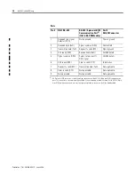
Страница 24: ...ort you must configure your cable to connect to the Allen Bradley cable Port 3 DH 485 Connector 1 Received line signal detector DCD Not applicable Chassis ground 2 Received data RxD Signal common GRD...

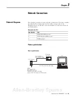
Страница 25: ...verter shown in each illustration Point to point Isolator Point to point Isolator Communication Port Item Number Port 1 RS 232 DB 9 DTE com port 2 RS 232 8 pin mini DIN com port 3 RS 485 com port AIC...

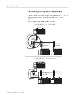
Страница 26: ...d by the AIC Interface Converter DH 485 Network using 1747 AIC Interface Converter 1747 PIC Interface Converter SLC 5 04 Processor SLC 5 02 Processor SLC 5 03 Processor 1747 AIC Isolated Link Coupler...

Страница 27: ...C Connection from Processor Channel 0 1761 CBL AP00 or 1761 CBL PM02 Cable 1747 CP3 or 1761 CBL AC00 Cable 1747 CP3 or 1761 CBL AC00 Cable 24V dc Power 24V dc user supplied SLC 5 03 or SLC 5 04 Proces...

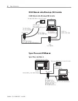
Страница 28: ...B 9 DTE com port 24V dc user supplied 1761 CBL AP00 or 1761 CBL PM02 Cable 1747 CP3 or 1761 CBL AC00 Cable 1761 CBL AP00 or 1761 CBL PM02 Cable MicroLogix 1000 Processor series C or later AIC Converte...

Страница 29: ...rt NULL Modem Adapter SLC DH 485 Network PC 1761 CBL AP00 or 1761 CBL PM02 Cable 1747 CP3 or 1761 CBL AC00 Cable 24V dc user supplied SLC 5 03 Processor 1747 AIC Isolated Link Coupler 24V dc user supp...

Страница 30: ...AC00 Cable PanelView Interface PC RJ45 Port 1761 CBL AM00 or 1761 CBL HM02 Cable 1761 CBL AS09 or 1761 CBL AS03 Cable 24V dc power 1747 CP3 or 1761 CBL AC00 Cable PC RJ45 Port 1761 CBL AM00 or 1761 C...

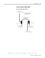
Страница 31: ...lied or from 24V dc terminals on SLC controller Extended DH 485 network 2438 m 8000 ft maximum and 32 nodes total 1761 CBL AM00 or 1761 CBL HM02 Cable DH 485 Network 1219 m 4000 ft Maximum 24V dc User...

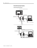
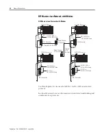
Страница 32: ...F1 Slave DF1 Master AIC Converter 1761 CBL AP00 or 1761 CBL PM02 Cable SLC 5 03 Processor CH0 Radio Modem or LeaseLine Straight 9 25 Pin Cable 1761 CBL AP00 or 1761 CBL PM02 Cable AIC Converter 1761 C...

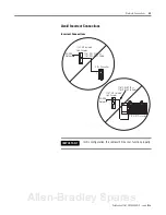
Страница 33: ...ctions IMPORTANT In this configuration the cable will fit but not function properly DH 485 Network 1761 CBL AS09 or 1761 CBL AS03 Cable 1747 AIC Isolated Link Coupler DH 485 Network 1761 CBL AS09 or 1...

Страница 34: ...Publication 1761 UM004B EN P June 2006 30 Network Connections...

Страница 35: ...ower OK On Power OK Off No power to AIC interface converter or dc source switch set incorrectly Power Source Selection Switch Cable 24V dc power supplied to AIC interface converter from device connect...

Страница 36: ...Publication 1761 UM004B EN P June 2006 32 Interpret the LED Indicators...

Страница 37: ...DF1 or User Network Number of nodes max 32 per multidrop network Length max 1219 m 4000 ft per multidrop network Number of ganged multidrop networks max 2 Attribute Value Operating Ambient Temperatur...

Страница 38: ...ex point to point isolator Yes 1 1 You can connect two DF1 Full duplex devices together with one AIC interface converter DF1 Master slave Yes 2 2 Any communication coming off of the RS 485 line will n...

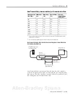
Страница 39: ...Transmit Delay time Communication Rate Kbps Min Delay ms Max Delay ms Typical Delay ms Pre send Transmit Delay Setting ms 1 1 The pre send transmit delay setting is used in your device s for example S...

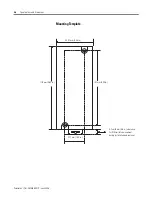
Страница 40: ...4B EN P June 2006 36 Specifications and Dimensions Mounting Template 52 07 mm 2 05 in 118 mm 4 64 in 107 mm 4 20 in 27 7 mm 1 09 in Allow 15 mm 0 6 in clearance for DIN rail latch movement during inst...

Страница 41: ...icators 31 M mount the AIC Advanced Interface Converter DIN rail 11 panel mount 12 mounting template 36 N networks components replaced by AIC Advanced Interface Converter 22 DF1 master slave network w...

Страница 42: ...Publication 1761 UM004B EN P June 2006 2 Index...

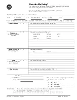
Страница 43: ...sary information is provided 1 2 3 Can we add more information to help you procedure step illustration feature example guideline other explanation definition Technical Accuracy all provided informatio...

Страница 44: ...NECESSARY IF MAILED IN THE UNITED STATES BUSINESS REPLY MAIL FIRST CLASS MAIL PERMIT NO 18235 CLEVELAND OH POSTAGE WILL BE PAID BY THE ADDRESSEE 1 ALLEN BRADLEY DR MAYFIELD HEIGHTS OH 44124 9705 PLEA...

Страница 45: ...Allen Bradley Spares...

Страница 46: ...rt rockwellautomation com Installation Assistance If you experience a problem with a hardware module within the first 24 hours of installation please review the information that s contained in this ma...

Отзывы: