background image

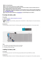
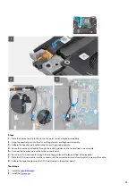
Steps
1. 
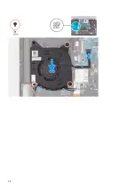
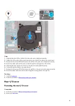
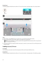
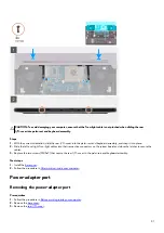
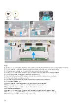
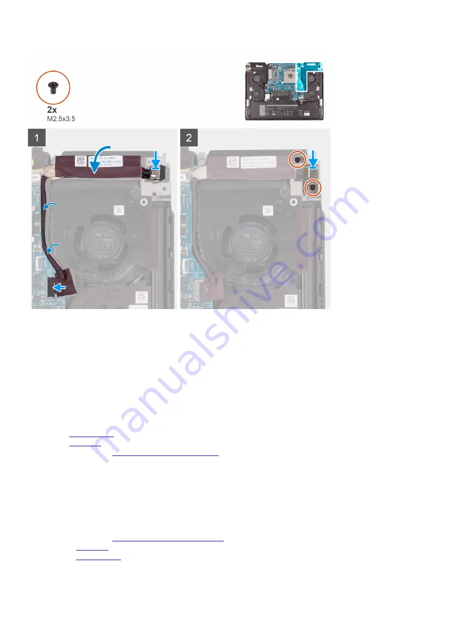
Align and place the power-adapter port into the slot on the palm-rest and keyboard assembly.
2. Adhere the power-adapter port cable to the fan and heat-sink assembly.
3. Connect the power-adapter port cable to the system board.
4. Route the power-adapter port cable through the routing guides on the fan and heat-sink assembly.
5. Place the power-adapter port bracket on the power-adapter port.
6. Align the screw holes on the power-adapter port bracket with the screw holes on the palm-rest and keyboard assembly.
7. Replace the two screws (M2.5x3.5) that secure the power-adapter port bracket to the palm-rest and keyboard assembly.

Next steps
1. 
Install the 

rear I/O-cover

.

2. Install the 

base cover

.

3. Follow the procedure in 

After working inside your computer

.

Headset port

Removing the headset port

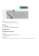
Prerequisites
1. 
Follow the procedure in 

Before working inside your computer

.

2. Remove the 

base cover

.

3. Remove the 

rear I/O-cover

.

33

Содержание P111F

Страница 1: ...Alienware x15 R1 Service Manual Regulatory Model P111F Regulatory Type P111F001 May 2021 Rev A00...

Страница 2: ...ntial damage to hardware or loss of data and tells you how to avoid the problem WARNING A WARNING indicates a potential for property damage personal injury or death 2021 Dell Inc or its subsidiaries A...

Страница 3: ...6 Battery cable 18 Wireless card 20 Solid state drive 23 Solid state drive bracket 24 Fans 26 Rear I O cover 29 Power adapter port 31 Headset port 33 Display assembly 36 Speakers 40 Touchpad 41 Keyboa...

Страница 4: ...ervice Tag or Express Service Code of your Dell computer 70 System diagnostic lights 70 SupportAssist diagnostics 71 Recovering the operating system 71 Flashing BIOS USB key 71 Flashing the BIOS 72 Wi...

Страница 5: ...iance WARNING Disconnect your computer from all power sources before opening the computer cover or panels After you finish working inside the computer replace all covers panels and screws before conne...

Страница 6: ...ction Touching the chassis before handling parts does not ensure adequate ESD protection on parts with increased sensitivity to ESD damage Handle all static sensitive components in a static safe area...

Страница 7: ...e only the inside of the bag is shielded Always place parts in your hand on the ESD mat in the system or inside an anti static bag Transporting Sensitive Components When transporting ESD sensitive com...

Страница 8: ...4 Connect your computer and all attached devices to their electrical outlets 5 Turn on your computer 8...

Страница 9: ...c surfaces Ensure that the screws are not left attached to such surfaces when replacing a component NOTE Screw color may vary with the configuration ordered Table 1 Screw list Component Secured to Scr...

Страница 10: ...1 5 5 Keyboard controller board Palm rest and antenna assembly M1 6x1 6 2 System board Palm rest and antenna assembly M2x4 5 Fan and heat sink assembly System board M2x3 9 I O board Palm rest and ante...

Страница 11: ...rd controller board 14 Wireless card 15 solid state drive 16 Left fan 17 Fan and heat sink assembly 18 Headset port 19 Power button NOTE Dell provides a list of components and their part numbers for t...

Страница 12: ...cover Prerequisites 1 Follow the procedure in Before working inside your computer About this task NOTE Before removing the base cover ensure that there is no micro SD card that is installed in the mi...

Страница 13: ...13...

Страница 14: ...rk on the sides to open the base cover 4 Lift and slide the base cover off the palm rest and keyboard assembly 5 Disconnect the battery cable from the system board 6 Press and hold the power button fo...

Страница 15: ...15...

Страница 16: ...Exercise caution when handling Lithium ion batteries Discharge the battery completely before removing it Disconnect the AC power adapter from the system and operate the computer solely on battery pow...

Страница 17: ...on an RTC reset cycle will occur When an RTC Reset cycle occurs the computer turns on and off three times An Invalid Configuration error message is displayed prompting you to enter the BIOS and confi...

Страница 18: ...the battery cable through the routing guides on the fan and connect the battery cable to the system board Next steps 1 Install the base cover 2 Follow the procedure in After working inside your compu...

Страница 19: ...the procedure in Before working inside your computer 2 Remove the base cover 3 Remove the battery NOTE If battery is disconnected from system board for service then there is a delay during boot as the...

Страница 20: ...the base cover 3 Follow the procedure in After working on your computer Wireless card Removing the wireless card Prerequisites 1 Follow the procedure in Before working inside your computer 2 Remove t...

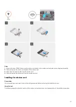
Страница 21: ...the antenna cables from the wireless card 4 Slide and remove the wireless card from the wireless card slot Installing the wireless card Prerequisites If you are replacing a component remove the existi...

Страница 22: ...AUX black triangle 2 Align and place the wireless card bracket on the wireless card 3 Align the notch on the wireless card with the tab on the wireless card slot and insert the wireless card at an an...

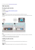
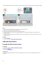
Страница 23: ...des a visual representation of the removal procedure Steps 1 Remove the screw M2x3 that secures the solid state drive thermal shield to the solid state drive and palm rest and keyboard assembly 2 Lift...

Страница 24: ...the solid state drive and palm rest and keyboard assembly 5 Replace the screw M2x3 that secures the M 2 2280 solid state drive thermal shield to the solid state drive and palm rest and keyboard assemb...

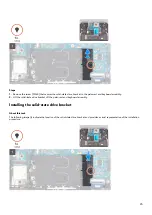
Страница 25: ...yboard assembly 2 Lift the solid state drive bracket off the palm rest and keyboard assembly Installing the solid state drive bracket About this task The following image s indicate the location of the...

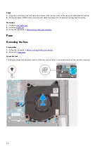
Страница 26: ...d keyboard assembly Next steps 1 Install the solid state drive 2 Install the base cover 3 Follow the procedure in After working inside your computer Fans Removing the fans Prerequisites 1 Follow the p...

Страница 27: ...palm rest and keyboard assembly 6 Remove the speaker cable and the antenna cable from the routing guides on the left fan 7 Disconnect the left fan cable from the system board 8 Peel the left fan cable...

Страница 28: ...28...

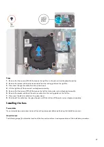
Страница 29: ...ft fan 5 Align and place the right fan into the slot on the palm rest and keyboard assembly 6 Connect the right fan cable to the system board 7 Replace the three screws M2x4 that secure the right fan...

Страница 30: ...r computer ensure that the Tron light cable has been disconnected from the system board before removing the rear I O cover 3 Firmly grasp the sides of your computer with both hands and push it outward...

Страница 31: ...d right Tron light cables into their respective connectors on the system board and close the latches to secure the cables 3 Replace the two screws M2 5x9 that secure the rear I O cover to the palm res...

Страница 32: ...cable from the system board and then remove it from the routing guides on the fan and heat sink assembly 4 Peel off the power adapter port cable from the fan and heat sink assembly 5 Lift the power a...

Страница 33: ...acket on the power adapter port 6 Align the screw holes on the power adapter port bracket with the screw holes on the palm rest and keyboard assembly 7 Replace the two screws M2 5x3 5 that secure the...

Страница 34: ...eadset port cable from the system board 5 Remove the headset port cable from the routing guides on the fan and heat sink assembly 6 Peel off the headset port cable from the fan and heat sink assembly...

Страница 35: ...able through the routing guides on the fan and heat sink assembly 5 Connect the headset port cable to the system board 6 Route the I O board cable through the routing guides on the fan and heat sink a...

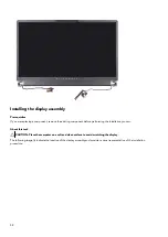
Страница 36: ...rocedure in Before working inside your computer 2 Remove the base cover 3 Remove the rear I O cover About this task NOTE The display assembly is a Hinge Up Display HUD and cannot be further disassembl...

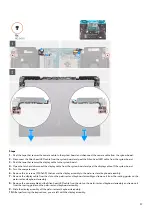
Страница 37: ...oard 5 Turn the computer over 6 Remove the six screws M2 5x3 5 that secure the display assembly to the palm rest and keyboard assembly 7 Remove the display cable from the slot on the palm rest and key...

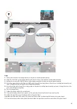
Страница 38: ...ng component before performing the installation process About this task CAUTION Place the computer on a soft and clean surface to avoid scratching the display The following image s indicate the locati...

Страница 39: ...rest and keyboard assembly 5 Route the display cable through the routing guides on the palm rest and keyboard assembly and route it through the slot on the palm rest and keyboard assembly 6 Turn the c...

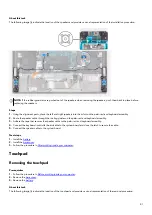
Страница 40: ...f the removal procedure Steps 1 Disconnect the speaker cable from the system board 2 Open the latch and disconnect the keyboard controller board cable from the system board 3 Peel the tape that secure...

Страница 41: ...and keyboard assembly 3 Adhere the tape that secures the speaker cable to the palm rest and keyboard assembly 4 Connect the keyboard controller board cable to the system board and close the latch to...

Страница 42: ...controller board cable from keyboard controller board 7 Fold up the keyboard controller board cable 8 Open the latch and disconnect the keyboard cable from the keyboard controller board 9 Fold up the...

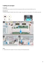
Страница 43: ...component before performing the installation process About this task The following image s indicate the location of the touchpad and provides a visual representation of the installation procedure Ste...

Страница 44: ...tape that secures the touchpad to the palm rest and keyboard assembly 12 Align the screw holes on the touchpad bracket to the screw holes on the palm rest and keyboard assembly 13 Replace the two scre...

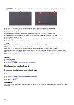
Страница 45: ...ontroller board cable from the keyboard controller board 7 Open the latch and disconnect the touchpad cable from the keyboard controller board 8 Open the latch and disconnect the keyboard cable from t...

Страница 46: ...latch to secure the cable 7 Slide the keyboard backlight cable into the connector on the keyboard controller board and close the latch to secure the cable 8 Align the screw holes on the keyboard contr...

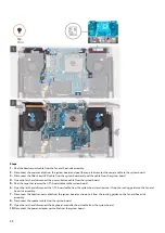
Страница 47: ...rs on your system board 1 Display cable 2 Alien head LED cable 3 Camera cable 4 Power button cable 5 I O board cable 6 Headset port cable 7 Speaker cable 8 Keyboard controller board cable 9 Power adap...

Страница 48: ...board 5 Peel the tape that secures the I O board cable to the system board 6 Open the latch and disconnect the I O board cable from the system board and remove it from the routing guides on the fan a...

Страница 49: ...sink assembly 19 Turn the system board assembly over 20 After performing all the above steps you are left with the system board CAUTION Do not use alcohol wipes to clean the Element 31 thermal grease...

Страница 50: ...button cable 5 I O board cable 6 Headset port cable 7 Speaker cable 8 Keyboard controller board cable 9 Power adapter port cable The following image s indicate the location of the system board and pro...

Страница 51: ...lign the screw holes on the system board assembly with the screw holes on the palm rest and keyboard assembly 5 Replace the five screws M2x4 that secure the system board assembly to the palm rest and...

Страница 52: ...rd assembly ensure that the power button board cable is placed on top of the system board Overlooking the power button board cable connection to the system board will result in no power failure after...

Страница 53: ...indicate the location of the fan and heat sink assembly and provides a visual representation of the removal procedure Steps 1 Turn the system board assembly over 2 Disconnect the left and right fan c...

Страница 54: ...d place the fan and heat sink assembly on the system board 2 Align the screw holes on the fan and heat sink assembly to the screw holes on the system board 3 In the sequential order 1 2 3 4 5 6 7 8 9...

Страница 55: ...tion procedure and avoids breaking the thermal bond between the system board and heat sink About this task The following image s indicate the location of the I O board and provides a visual representa...

Страница 56: ...hermal bond between the system board and heat sink 2 Install the solid state drive bracket 3 Install the rear I O cover 4 Install the fans 5 Install the solid state drive 6 Install the wireless card 7...

Страница 57: ...eyboard backlight cable 3 Peel the tape that secures the antenna cable to the keyboard bracket 4 Remove the antenna and speaker cables from the routing guides on the keyboard bracket 5 Lift the speake...

Страница 58: ...ket 7 Adhere the tape that secures the antenna cable to the keyboard bracket 8 Move the speaker cables on top of the keyboard Next steps 1 Follow the procedure from step 3 to step 20 in Installing the...

Страница 59: ...eat sink This simplifies the removal and installation procedure and avoids breaking the thermal bond between the system board and heat sink About this task The following image s indicate the location...

Страница 60: ...2x1 9 that secure the power button bracket to the palm rest and keyboard assembly 4 Replace the two screws M1 2x1 5 that secure the power button bracket to the palm rest and keyboard assembly Next ste...

Страница 61: ...e speakers 13 Remove the touchpad 14 Remove the keyboard controller board 15 Remove the system board NOTE The system board can be removed and installed along with the heat sink This simplifies the rem...

Страница 62: ...I O board 4 Install the system board NOTE The system board can be removed and installed along with the heat sink This simplifies the removal and installation procedure and avoids breaking the thermal...

Страница 63: ...Drivers and downloads When troubleshooting downloading or installing drivers it is recommended that you read the Dell Knowledge Based article Drivers and Downloads FAQ SLN128938 63...

Страница 64: ...Moves to the previous field Down arrow Moves to the next field Enter Selects a value in the selected field if applicable or follow the link in the field Spacebar Expands or collapses a drop down list...

Страница 65: ...SSD device information of the computer M 2 PCIe SSD 2 Display the M 2 PCIe SSD device information of the computer AC Adapter Type Displays the type of AC adapter System Memory Displays the size of mem...

Страница 66: ...ustom charge start and stop Default Adaptive Advance Battery Charge Configuration Set the battery charge settings with a preselected custom charge start and stop Default Adaptive Power on LID open Sel...

Страница 67: ...Security Mitigations Table It allows the system firmware to confirm to the OS that certain security best practices have been implemented in the System Management Mode SMM software Default Disabled Fir...

Страница 68: ...ta on your computer CAUTION Anyone can access the data stored on your computer if it is not locked and left unattended NOTE System and setup password feature is disabled Assigning a system setup passw...

Страница 69: ...t Setup Password alter or delete the existing setup password and press Enter or Tab NOTE If you change the System and or Setup password re enter the new password when prompted If you delete the System...

Страница 70: ...pre defined beep codes indicating various failures For example the power and battery status light blinks red two times followed by a pause and then blinks blue three times followed by a pause This 2 3...

Страница 71: ...s it automatically starts Dell SupportAssist OS Recovery Dell SupportAssist OS Recovery is a standalone tool that is preinstalled in all Dell computers installed with Windows 10 operating system It co...

Страница 72: ...le to access the internet due to WiFi connectivity issues a WiFi power cycle procedure may be performed The following procedure provides the instructions on how to conduct a WiFi power cycle NOTE Some...

Страница 73: ...attery 5 Press and hold the power button for 20 seconds to drain the flea power 6 Install the battery 7 Install the base cover 8 Connect the power adapter to your computer 9 Turn on your computer NOTE...

Страница 74: ...uniquely identified by a Service Tag or Express Service Code To view relevant support resources for your Dell computer enter the Service Tag or Express Service Code at www dell com support For more in...

Отзывы: