background image

Installing liquid cooling module

NOTE: Ensure that you remove the security cable and security screw from the security-cable slot—if applicable.

1.

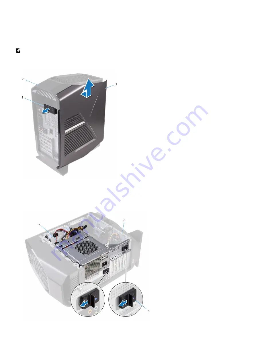
Pull the side-panel release latch.

2.

Release the left-side cover away from the chassis and then lift it from the computer.

1. side-panel release latch

2. top cover

3. left-side cover

3.

Lay the computer on the right side.

4.

Slide the power-supply unit cage release latches towards the unlock position.

1. power-supply unit

2. chassis

6

Содержание Aurora R6 D23M

Страница 1: ...Aurora R6 Liquid Cooling Module Regulatory Model D23M Regulatory Type D23M001...

Страница 2: ...ge to hardware or loss of data and tells you how to avoid the problem WARNING A WARNING indicates a potential for property damage personal injury or death 2018 2019 Dell Inc or its subsidiaries All ri...

Страница 3: ...e working inside your computer 4 Before you begin 4 Safety instructions 4 Recommended tools 4 2 Installing liquid cooling module 6 3 After working inside your computer 16 4 Getting help and contacting...

Страница 4: ...ers panels and screws before connecting to the electrical outlet CAUTION To avoid damaging the computer ensure that the work surface is flat and clean CAUTION Handle components and cards with care Do...

Страница 5: ...Plastic scribe 5...

Страница 6: ...icable 1 Pull the side panel release latch 2 Release the left side cover away from the chassis and then lift it from the computer 1 side panel release latch 2 top cover 3 left side cover 3 Lay the com...

Страница 7: ...upply unit cage while pressing and holding the graphics card bracket 1 power supply unit cage 2 graphics card bracket 3 chassis 6 Rotate the power supply unit cage away from the chassis 1 power supply...

Страница 8: ...9 Lift the processor fan and heat sink assembly off the system board 1 processor fan cable 2 captive screws 4 3 processor fan and heat sink assembly 10 Remove the screw that secures the top chassis fa...

Страница 9: ...towards the chassis until the unit snaps into place 14 Stand the computer right side up 15 Carefully pry around the edges of the right side cover from the chassis 1 chassis 2 right side cover 16 Disco...

Страница 10: ...is 19 Disconnect the lighting cable from the top cover 20 Slide the lighting cable through the slot on the chassis 1 lighting cable 2 chassis 3 screws 2 4 top cover 21 Starting from the back release t...

Страница 11: ...lace the screws that secure the radiator and fan assembly to the radiator and fan cage 27 Align the screw holes on the processor cooler with the screw holes on the system board 28 In sequential order...

Страница 12: ...aptive screws 4 30 Align the screw holes on the VR heatsink with the screw holes on the system board 31 Tighten the captive screws that secure the VR heatsink to the system board 1 VR heatsink 2 capti...

Страница 13: ...cage 34 Slide the lighting cable through the slot on the chassis 35 Align the tabs on the top cover with the slots on the chassis and snap the top cover into place 1 top cover 2 slot 3 lighting cable...

Страница 14: ...over 38 Connect the lighting cable to the right side cover a chassis b lighting cable c right side cover d tabs e slots 39 Align the tabs on the right side cover with the slots on the chassis and snap...

Страница 15: ...chassis b slots c right side cover 40 Align the tabs on the left side cover with the slots on the chassis 41 Snap the left side cover to lock it in place 1 chassis 2 slots 3 tabs 4 left side cover 15...

Страница 16: ...sure that no stray screws remain inside your computer 2 Connect any external devices peripherals or cables you removed before working on your computer 3 Replace any media cards discs or any other part...

Страница 17: ...p blogs drivers software updates and so on www alienware com gamingservices Videos providing step by step instructions to service your computer www youtube com alienwareservices Contacting Alienware T...

Отзывы: