


6
www.observint.com
© 2018 Observint Technologies. All rights reserved.
maintenance cable to the connector on the maintenance panel, and then attach it to CVBS monitor to see a
live view video from the camera.
1.
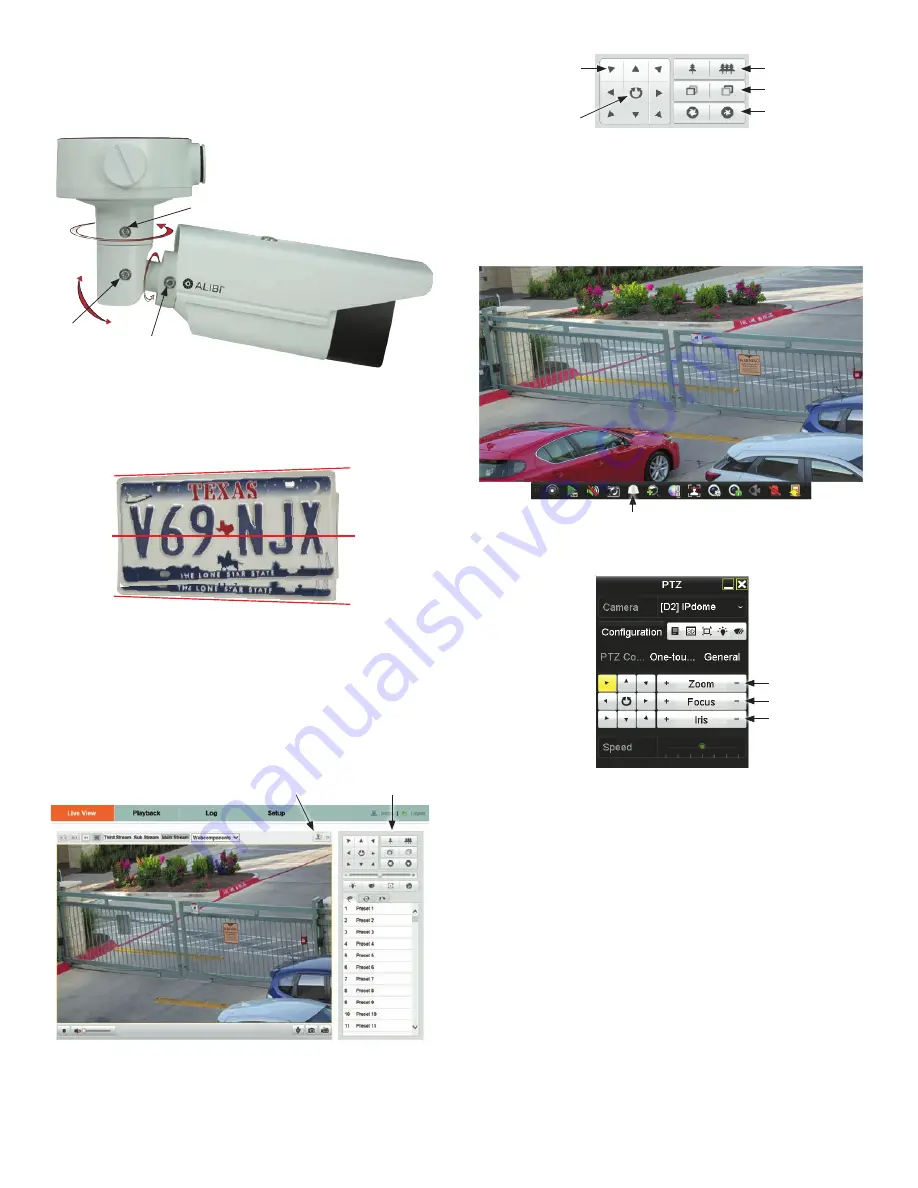
While observing live video from the camera, use the L-wrench to loosen the adjustment bracket lock
screw on the back of the adjustment bracket until the camera is free to move and rotate.
Pan lock screw - Pan: 0˚ ~ 360˚
Tilt lock screw
Tilt: 0˚ ~ 100˚
Rotation lock screw
Rotation: 0˚ ~ 360˚
2.
Point the camera at your surveillance target, changing the pan and tilt as needed. Be certain to stay
within the specified pan and tilt ranges of the camera. See above.
3.
When the camera is installed, adjust the camera rotation so that the tilt of the licence plate is no
more than ± 5º. Consider the plane of the road surface when making the adjustment.
5º
5º
0º
4.
Tighten the adjustment bracket lock screw to securely hold the camera in place.
Step 7. Verify PTZ functionality
Use the PTZ control panel to exercise the zoom and focus functionality of the camera. Accessing to the
control panel depends on whether the camera is installed as a device on a LAN or if it is connected to a
NVR. Select the installation type below for your camera to complete this step.
For cameras installed on a LAN
1.
Log into the camera and then open the
Live View
window.
Open / Close PTZ Control Panel
PTZ Control Panel
2.
Click the joystick icon to open the PTZ control panel. See above.
3.
In the PTZ control panel, click each
zoom
and
focus
button shown in the graphic below. Verify
that the camera performs as expected. Refer to the
Specifications
section of this document for zoom
range.
Direction buttons
Zoom In / Out
Focus In / Out
Iris Open / Close
Continuous
pan
For cameras connected directly to an NVR
Refer to the firmware manual for your NVR for specific instructions to perform the following:
1.
Log into the NVR at the NVR console.
2.
In the
Live View
display, find the PTZ camera you installed. Click on the camera to open the Quick
Setting toolbar.
PTZ Control icon
3.
Click the
PTZ Control
icon. See above.
4.
In the pop-up PTZ menu, click the
PTZ Control
tab. See below.
Zoom In / Out
Focus In / Out
Iris Open / Close
5.
In the PTZ Control panel, click the zoom and focus buttons labeled in the graphic above. Verify that
the camera performs as expected. Refer to the
Specifications
section of this document for motion
and zoom ranges.
Step 8. Adjust the camera image for your surveillance target
Use the firmware menus to adjust the brightness, contrast, saturation and sharpness of the video image
if necessary. These settings are initially optimized at the factory and may not need adjustment. When
adjustments are necessary, the paths to the image settings menus are different if the camera is installed
as a device on a LAN, or if it is connected to a NVR. Select the installation type below for your camera to
complete this step.
For cameras installed on a LAN
1.
If necessary, log into the camera on the LAN with administrative credentials.
2.
After adjusting the camera for the a typical field of view, click the
Setup
tab, and then click the
Image
link in the left frame.


