


3
www.observint.com
© 2018 Observint Technologies. All rights reserved.
Camer
a
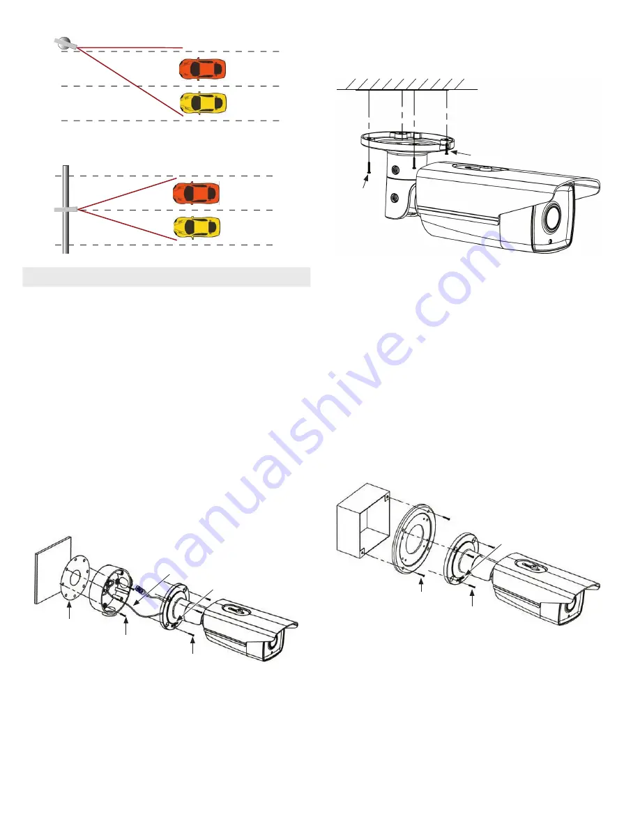
The figures below show an application for two lanes of traffic with the camera mounted in the
middle of a crossbar.
Camera
NOTE
Whether mounting the camera on a pole or crossbar, ensure that it does not vibrate when heavy
vehicles pass or for other events..
Step 2. Install the camera
The camera includes hardware to install it directly to the Junction box provided, to a mounting surface
(without the junction box), or to a double-gang electrical box using the adapter plate provided. When
using the junction box, camera LAN and power drop cables can attach to extension cables inside the box.
The camera with or without the junction box can be installed on a ceiling (horizontal surface) or wall
(vertical surface). To install the camera, do one of the following:
To mount the camera using the Junction box
1.
Remove the cover on the underside of the camera, and then install a microSD card. The card can
have a capacity up to 128 GB. Reinstall the cover.
2.
Determine the best fasteners for securing the Junction box to mounting surface. The mounting
hardware provided is suitable for most surfaces.
3.
Remove the junction box from the camera assembly by loosing the four captive screws.
4.
Attach the drill template to the surface. Mark the location of the Junction box mounting screw
holes. If routing extension cables for the LAN, power, alarm devices, etc. through the mounting
surface, mark the location for that hole too.
NOTE
: When installing the box onto a wall, observe the
orientation for TOP and BOTTOM orientation markings inside the box and on the camera mounting
base, and orient the drill template properly.
Mounting surface
Orientation mark
Mounting base screws (4)
Junction box mounting screws (4)
Drill template
Safety cable
Junction box
Camera
5.
Drill holes in the mounting surface for the mounting screws and extension cables (if necessary).
6.
Secure the Junction box to the mounting surface using appropriate fasteners.
7.
Attach the camera safety cable to the safety hook inside the junction box.
8.
Route the network LAN, audio, alarm and power extension cables between the junction box and the
devices they connect to. Do not apply power to the extension cables at this time.
9.
Connect the extension cables to the camera drop cables.
10. Secure the camera to the junction box with four (4) screws.
11. Apply power to the camera.
To mount the camera onto a surface without the junction box
For this mounting option, the drop cables can be routed through the mounting surface, or through the
cable channel in the mounting base.
Mounting surface
Cable channel
Camera
Mounting base
screws (4)
1.
Determine the best fasteners for securing the camera mounting base to mounting surface. The
mounting hardware provided may be suitable for some surfaces.
2.
Remove the junction box from the camera assembly by removing the four mounting base captive
screws.
3.
Using the camera mounting base as a template, mark the locations of the holes for the mounting
screws. Also mark the location of a hole for the camera drop cables if needed.
4.
Route the network LAN, audio, alarm and power extension cables between the camera and the
devices they connect to.
5.
Connect the extension cables to the camera drop cables.
6.
Secure the camera to the mounting surface with four (4) screws.
7.
Apply power to the camera.
To mount the camera onto an electrical box
1.
Install a double-gang electrical box at the location where the camera will be installed.
2.
Attach the gang box adapter plate provided to the electrical box using four (4) screws.
Double-gang box
Adapter plate
Orientation mark
Mounting base screws (4)
Adapter plate mounting screws (4)
Camera
3.
Remove the junction box from the camera assembly by loosing the four mounting base captive
screws.
4.
Attach the adapter plate to the double-gang box using at least two (2) screws.
5.
Route the network LAN, audio, alarm and power extension cables between the devices they connect
to and out through the adapter plate. Do not apply power to the extension cables at this time.
6.
Connect the extension cables to the camera drop cables.
7.
Secure the camera to the adapter plate with four (4) screws.
8.
Apply power to the camera.


