6. Maintenance
22
Read the instructions carefully. The items refer to the parts list and service kits section.
Drawing 1 to 7
Gear Train
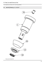
Turn to (drawing 3): Reassemble the internal components of the Gearhead (26). Make sure to lightly repack it with grease as it
reassembled. Check that the Gearhead Screws (46) are tight.
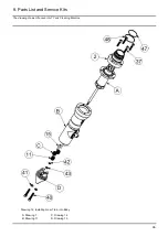
Turn to (drawing 7): Place the Output Shaft (12) over the output shaft of the (26). Align the flat with the Output Shaft Set Screw
(39). Alfa Laval Tank Equipment Inc. recommends using a new (39)
during reassembly. Using a 0.050” (1.27 mm) Hex Key,
screw into the (12). The (39) should fall into the dimple on the output shaft of the (26).
Turn to (drawing 4): Check that the (23) and (55) are inside and (54) is on the (27).
Turn to (drawing 5): Insert the input shaft & input pinion (22) & (51) assembly through the (27).
Turn to (drawing 7): Push the Rotor Shaft Lower Bearing (27) into Rotor Shaft Bearing Housing (57).
Ensure that the thin spacer is on the (26) top idler gears.
Engage the (51) into the (26). This can be made easier by extending the (22) assembly slightly from the (57) assembly.
Push the (57) into the Gearhead Housing (8), aligning the Gearhead Pin (53) with the keyway of the (8).
Turn to (drawing 6): Place the Rotor (10) (Carbide Bearing (58) down) over the Input Shaft (22).
Using a 3/16” (4.7 mm) socket, screw the Nut (43) and Lockwasher (42) onto the top of the Input Shaft.
Place the (14) assembly (O-ring side first) over the (12) and push and twist it into the Gearhead Housing (8) until it is flush and
fully seated.
The captured air will try to push the ends of the assembly off, so, quickly insert this assembly into the Stem (3) and proceed to
the next section.
Drawing 14
Stem Cap
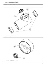
Place the Stem Cap (2) on the (57), making sure the screw holes are aligned.
Using a 3/32” (2.4 mm) Hex Key, screw the stem cap screw (37) into the Stem (3). Tighten in a star pattern.
Drawing 12, 14
Base assembly
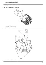
Turn to (drawing 14): Place the Output Pinion (11) (round opening down) onto the Output Shaft (12).
Insert the Idler Shafts (15) into their respective holes in the Idler Shaft Base (29).
Turn to (drawing 12): Install the Idler Gears (16) (Idler Gear Bushing (31) down) onto the Idler Shafts. Twisting the Tee Housing
(4) slightly will help the Idler Gears drop into place.
Turn to (drawing 14):
Using a 3/16” (4.7 mm) socket, screw the Nut (43) and the Lockwasher (42) onto the Output Shaft.
Put the Base (28) back onto the Tee Housing.
Using a 7/64” (2.8 mm) Hex Key, screw the (40) and Lockwashers (41) into the Idler Shaft Base (29).
Drawing 16
Stator and inlet collar
Rotate the Rotor (10) using a small Hex Key. It should spin fairly easily and its veins must not strike the walls of the Stem Cap
(2). Continue turning the Rotor. The Nozzle and Tee Housing will slowly rotate if everything has been assembled correctly.
Insert the Stator (9) into the (2).
Screw on the Inlet Collar (1) (hand-tight only), and tighten the Inlet Collar Set Screw (38)
with a 5/64” (2 mm) Hex Key.
This completes the reassembly process.
Содержание GJ 7
Страница 2: ......
Страница 46: ...8 Parts List and Service Kits 43 Appendix A AL GJ 7 For Low Pressure Applications ...


