Alfa Laval CPM-2 Скачать руководство пользователя страница 16

18

Study the instructions carefully.
The items refer to the parts list and service kits section.
Lubricate the guide, the sectors and the threads before assembly.
CPMI-2: Constant-Pressure Modulating Inlet. CPMO-2: Constant-Pressure Modulating Outlet.
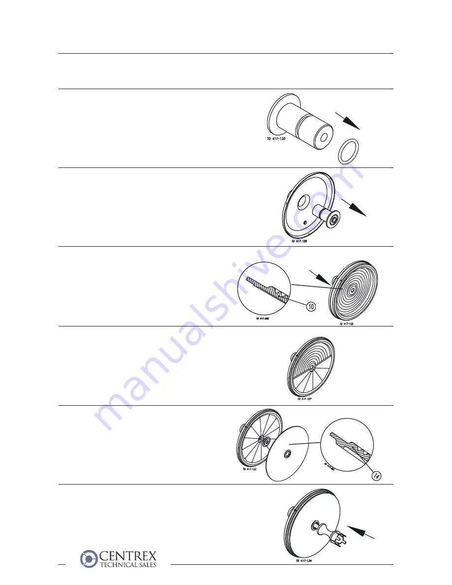
Step 1

Fit O-ring (8)

Step 2

Lubricate guide (9) and fit it into cover (7).

NOTE!

Turn cover (7) downwards before continuing.

Step 3

Fit upper diaphragm (10), upper inner ring (11) and outer ring
(13) on guide (9) and cover (7).

NOTE!

The upper diaphragm has a small recess.The outer ring must
be fitted with the recess turned uppermost so that the
indication hole is fixed opposite the indication hole in the cover.

Step 4

Fit sectors (12) between upper inner ring (11)  and outer ring
(13).

Step 5

Fit lower inner ring (11) and lower diaphragm (14).
Concentric grooves should point towards the steel segments.

Step 6
CPMI-2:

Fit plug (15a) in the diaphragm unit and guide (9) until the flange
of the plug contacts lower diaphragm (14).

Fit the correct diaphragm!

(Air side)

Fit the correct diaphragm!

4.3 Assembly

4. Maintenance


Содержание CPM-2

Страница 1: ...IM70775 EN4 20 0 CPM 2 Constant Pressure Modulating Valve Instruction Manual...

Страница 2: ...clare that Denomination Type Year Declaration of Conformity The designating company Designation Constant Pressure Modulating Valve CPM 2 Bjarne S ndergaard Manager Product Centres Compact Heat Exchang...

Страница 3: ...lation 7 2 1 Unpacking Delivery 7 2 2 General installation 8 2 3 Welding 9 2 4 Fitting of Booster optional extra 10 3 Operation 12 3 1 Operation 12 3 2 Fault finding 13 3 3 Recommended cleaning 14 4 M...

Страница 4: ...upplied to the valve The valve and the pipelines must never be pressurised when dismantling the valve Operation Always observe the technical data see chapter 5 Always release compressed air after use...

Страница 5: ...cases metal straps Wood and cardboard boxes can be reused recycled or used for energy recovery Plastics should be recycled or burnt at a licensed waste incineration plant Metal straps should be sent...

Страница 6: ...ions Thermal expansion of the tubes Excessive welding Overloading of the pipelines Step 4 Fittings Ensure that the connections are tight Step 5 Air connection Step 6 Air pressure regulating valve opti...

Страница 7: ...he minimum clearance so that the internal valve parts can be removed Step 1 Dismantle the valve in accordance with steps 1 4 in section 4 2 Pay special attention to the warning Step 3 CPMO 2 1 Weld th...

Страница 8: ...n Booster housing 1 Step 2 1 Remove the valve top in accordance with step 3 in section 4 2 Pay special attention to the warnings 2 Fit Booster housing 1 on the cover 3 Fit and tighten lock nut 2 Step...

Страница 9: ...7 Compressed air An air pressure compensating regulating valve must be used and should be installed with min clearance to the Booster CPM 2 valve The pressure regulating valve PR and the pressure gaug...

Страница 10: ...ay special attention to the warnings The items refer to the parts list and service kits section Step 5 Lubrication 1 Ensure smooth movement between diaphragms 10 14 and support sectors 12 2 Ensure smo...

Страница 11: ...ect type pressure compensating Product leakage Worn diaphragm Replace the diaphragm Product affected diaphragm Air leakage Worn O ring Replace the O ring Worn diaphragm 10 Replace the diaphragm Worn a...

Страница 12: ...imum CIP flow 2 0 5 by weight HNO3 at 700 C 158 F Step 6 1 Avoid excessive concentration of the cleaning agent Dose gradually 2 Adjust the cleaning flow to the process Milk sterilization viscous liqui...

Страница 13: ...of the valve Use the statistics for planning of inspections Replace after leakage Lubrication Before assembly Guide Molycote longtherm 2 Plus Sectors Molycote 111 Threads Molycote TP42 Maintain the va...

Страница 14: ...ernal parts of the valve from valve body 16 Step 3 CPMI 2 and CPMO 2 valves Remove top nut 1 washer 2 and top 3 from plug 15a or 15b Step 4 Remove plug 15a from the diaphragm unit and guide 9 or for C...

Страница 15: ...enance Step 7 Remove outer ring 13 upper inner ring 11 and upper diaphragm 10 Step 8 Remove guide 9 from cover 7 Step 9 Remove O ring 8 from guide 9 Step 10 Replace the O ring and the diaphragms 4 2 D...

Страница 16: ...d outer ring 13 on guide 9 and cover 7 NOTE The upper diaphragm has a small recess The outer ring must be fitted with the recess turned uppermost so that the indication hole is fixed opposite the indi...

Страница 17: ...9 until the flange of the plug contacts lower diaphragm 14 Step 9 Fit top 3 washer 2 and top nut 1 on plug 15a or 15b Step 10 Fit and torque tighten clamp 6 to 10 15Nm 7 5 11 lbf ft Step 11 Pre use c...

Страница 18: ...ernative size regulating area Approx 15m3 h 66 gal m CIP area Materials Product wetted steel parts AISI 316 L Other steel parts AISI 304 Upper diaphragm Nitrile NBR standard Lower diaphragm PTFE cover...

Страница 19: ...200 C 68 F Measurement In accordance with VDI 2173 Example 2 CPMI 2 Pressure drop p 300 kPa 43 5 psi Flow Q 1 m3 h 4 4 gal m Select CPMI 2 Kv 2 15 which at working point will be approx 35 open equal...

Страница 20: ...13 1 Outer ring 14 1 Lower diaphragm 15 1 Valve plug 16 1 Valve body Service kits product wetted parts The drawing and the parts list include all items 6 Parts lists and service kits 6 1 CPM 2 Denomi...

Страница 21: ...MI 2 Constant Pressure Modulating Inlet CPMO 2 Constant Pressure Modulating Outlet The drawing includes all items of the valve The items refer to the parts list on the opposite part of the page 6 Part...

Страница 22: ...list include all items Parts list Pos Qty Denomination 1 1 Booster housing 2 1 Lock nut 3 1 Washer 4 1 Spring washer 5 1 Nut 6 1 Booster piston 7 1 Diaphragm 8 1 Booster cover 9 1 Clamps and screws S...

Страница 23: ...25 6 Parts lists and service kits 6 2 Booster The drawing below shows the Booster The items refer to the parts list on the opposite part of the page The drawing includes all items of the valve...

Отзывы: