background image

Garden Utility Cart

User Manual

4

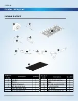
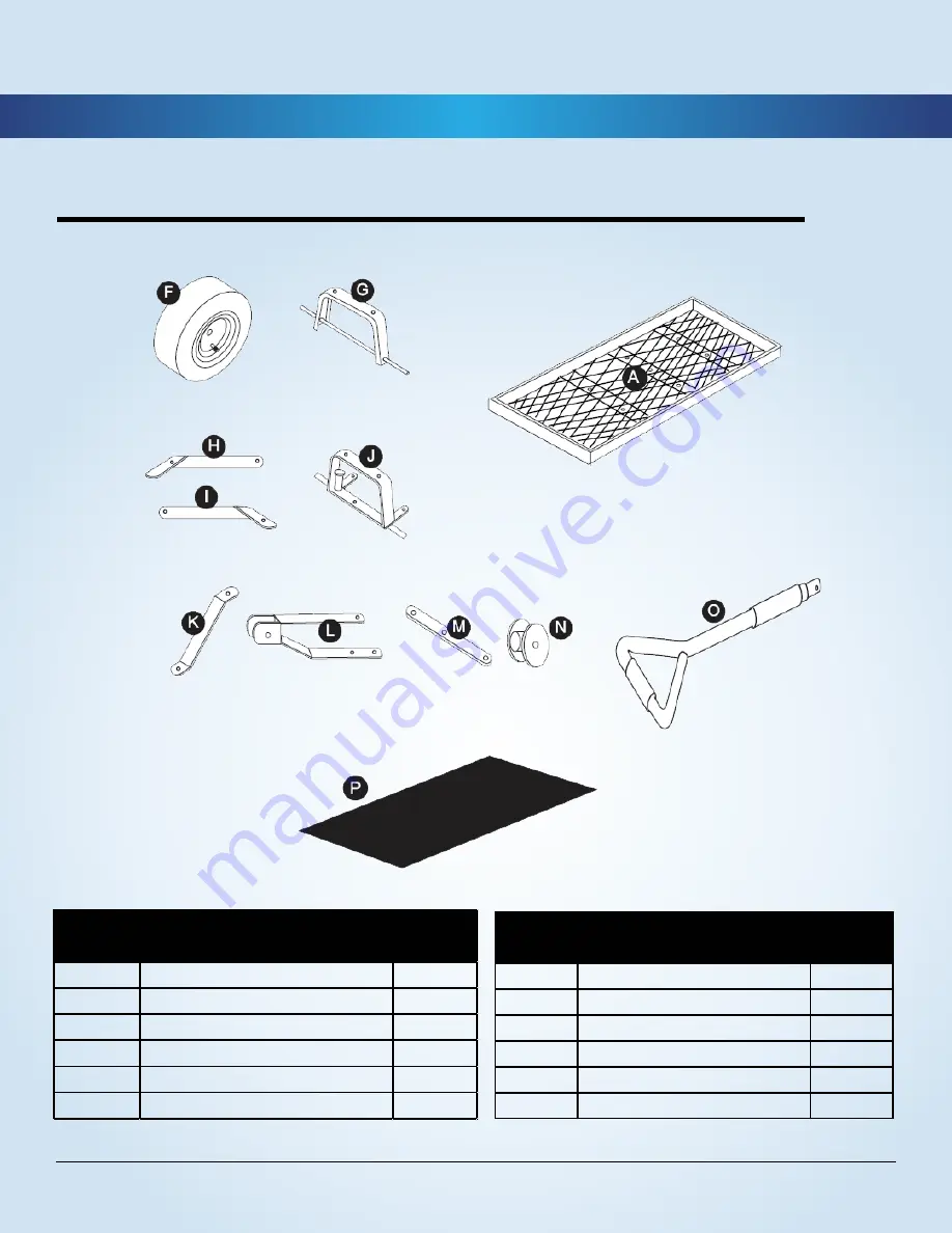
PACKAGE CONTENTS

2

Diagram 

Letter

Description

Quantity

A

Cart Bed

1

F

Wheels

4

G

Rear Axle Support

1

H

Left Rear Axle Brace

1

I

Right Rear Axle Brace

1

J

Front Axle Support

1

Diagram 

Letter

Description

Quantity

K

Center Front Axle Brace

1

L

Yoke

1

M

Steering Link Connector

1

N

Plastic Coupling

1

O

Pull Handle

1

P

Removable Rubber Liner

1

Содержание 52377

Страница 1: ...GARDEN UTILITY CART UTILIDAD DE JARDÍN CESTA User Manual Manual de usuario English 02 Español 11 ...

Страница 2: ...en Utility Cart User Manual Safety information and Warnings 3 Preparation 3 Tools Needed 3 Package Contents 4 Hardware Contents 5 Assembly Instructions 6 9 Care and Maintenance 9 Exploding Assembly Drawing 10 ...

Страница 3: ...e used for highway use Always distribute the load evenly over the surface of the cart bed If any part of this cart becomes damaged broken or misplaced do NOT use this cart until a replacement part has been obtained Do NOT operate this cart on surfaces or roll over objects that could cause damage to the pneumatic tires or tubes Use only a hand held air pump to inflate the tires Save these instructi...

Страница 4: ...ty A Cart Bed 1 F Wheels 4 G Rear Axle Support 1 H Left Rear Axle Brace 1 I Right Rear Axle Brace 1 J Front Axle Support 1 Diagram Letter Description Quantity K Center Front Axle Brace 1 L Yoke 1 M Steering Link Connector 1 N Plastic Coupling 1 O Pull Handle 1 P Removable Rubber Liner 1 ...

Страница 5: ...Garden Utility Cart User Manual 5 HARDWARE CONTENTS 3 ...

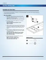
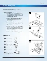
Страница 6: ... each bolt NOTE Hand tighten the connection Do not tighten completely c Insert the end of the left rear axle brace H onto the side of the rear axle support with the welded spacer bushings facing outward Repeat this step for the right rear axle brace I d Align the holes on the flat ends of the left and right axle braces with carriage support bolts II which are welded on the bed of the cart NOTE If ...

Страница 7: ... J by using the retainer washer MM and cotter pin L see Fig 2 1 c Attach the center front axle brace K and yoke L to the front axle support J by using long steering bolts OO 6 mm washers QQ and 6 mm lock nut PP see Fig 2 2 d Attach the steering link connector M to the front axle support J and yoke L by using three short steering bolts NN 6mm washers QQ and 6 mm lock nuts PP see Fig 2 2 NOTE Leave ...

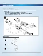
Страница 8: ...ONS continued 6 4 WHEEL ASSEMBLY a Place the wheels F onto the ends of the front and rear axle supports b Insert a 12 mm washer HH and a Cotter Pin LL onto the end of each wheel see Fig 3 c Put the axle cap KK into the end of the rear axle Hardware Used ...

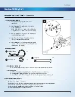
Страница 9: ... a lock pin CC see Fig 4 Hardware Used Large Lock Pin 8 mm Washer Large Pin x 1 x 1 x 1 6 RUBBER MAT ASSEMBLY a Place the rubber mat Q onto the cart bed This can be removed if not needed 7 TIRE INFLATION a Before attempting to operate the cart check the air pressure of each tire b If additional inflation is needed use only a hand operated air pump c Do NOT exceed 30 PSI as damage to the tires and ...

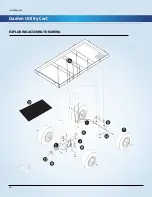
Страница 10: ...Garden Utility Cart User Manual 10 EXPLODING ASSEMBLY DRAWING 8 ...

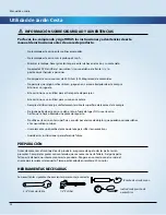
Страница 11: ...uario 11 Información Sobre Seguridad Y Advertencias 12 Preparación 12 Herramientas Necesarias 12 Contenido Del Paquete 13 Contenido De Hardware 14 Instrucciones De Montaje 15 18 Cuidado Y Mantenimiento 18 Estallido De Dibujo De Montaje 19 ...

Страница 12: ...era Siempre distribuir la carga uniformemente sobre la superficie de la cama de la compra Si alguna parte de este carro se daña roto o fuera de lugar NO use este carro hasta que se haya obtenido una pieza de repuesto No utilice este carro en las superficies o rodar por encima de objetos que pueden ocasionar daños a los neumáticos o tubos Use solamente una bomba de mano del aire para inflar los neu...

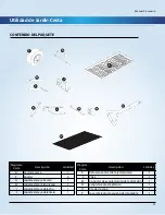
Страница 13: ...4 G soporte del eje trasero 1 H soporte del eje izquierdo 1 I soporte del eje derecho 1 J soporte del eje delantero 1 Diagrama Carta descripción cantidad K Refuerzo central del eje delantero 1 L Yoke 1 M Conector de acoplamiento de la dirección 1 N acoplamiento de plástico 1 O tire del mango 1 P revestimiento de caucho desmontable 1 ...

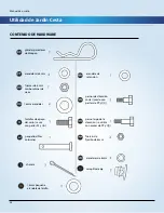
Страница 14: ...s de cierre 16mm arandelas tornillos de apoyo del carro se usa con partes FF y GG pequeño alfiler columnar chaveta 16mm pequeña arandela del anillo arandela de retención pernos de dirección cortas usado con partes de PP y QQ perno largo de la dirección se utiliza con piezas de PP y QQ Tuercas de fijación de 6mm arandelas de 6mm casquillo de eje ...

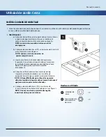
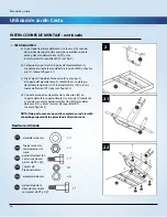
Страница 15: ...e completamente c Inserte el extremo de la abrazadera del eje trasero izquierdo H en el lado del soporte del eje trasero con los soldados bujes espaciadores orientada hacia fuera Repita este paso para el eje trasero derecho abrazadera I d Alinee los orificios de los extremos planos del eje izquierda y derecha abrazaderas con tornillos de apoyo del carro II que se sueldan en la cama del carro NOTA ...

Страница 16: ...o J mediante el uso de largo de la dirección pernos OO 6 arandelas mm QQ y 6 mm tuerca de fijación PP véase la figura 2 2 d Conecte el conector de enlace de la dirección M en la parte delantera soporte del eje J y el yugo L mediante el uso de tres cortos pernos de dirección NN arandelas de 6 mm QQ y 6 mm tuercas de seguridad PP véase la figura 2 2 NOTA Deje por lo menos una vuelta completa en cada...

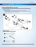
Страница 17: ...A a Coloque las ruedas F en los extremos de la parte frontal y los soportes del eje trasero b Inserte una arandela 12 mm HH y un pasador de chaveta LL en el extremo de cada rueda ver fig 3 c Colocar el tapón del eje KK en el extremo del eje trasero Hardware utilizado 16mm arandelas chaveta casquillo de eje ...

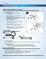
Страница 18: ...rdware utilizado x 1 x 1 x 1 6 GOMA MAT ASAMBLEA a Coloque la alfombrilla de goma Q en la cama de la compra Esto puede ser removido si no es necesario 7 INFLADO DE LLANTAS a Antes de intentar operar el carro comprobar la presión de aire de cada neumático b Si se necesita la inflación adicional use sólo una bomba de aire accionada manualmente c No exceda 30 PSI ya que podrían provocar daños en los ...

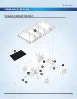
Страница 19: ...Utilidad de Jardín Cesta Manual de usuario 19 ESTALLIDO DE DIBUJO DE MONTAJE 8 ...

Страница 20: ...YEAR WARRANTY AÑOS DE GARANTÍA USA 1 866 446 2063 MODEL RP ALGE M PRODUCT CODE 52377 03 2017 2 DISTRIBUTED BY DISTRIBUIDO POR ALDI INC BATAVIA IL 60510 WWW ALDI US ...

Отзывы: