Rigging manual LR24 Rev. 1.21
18
5. Array configurations ___________________________________________
Landing the array compression mode
De-compress the cabinets to 0° by releasing the tension of the lever hoist. The whole array should now be hanging vertical. Remove the PBFRML24 and attach
the PRRGL24 pre-rig. This is a two man job. The pre-rig angle arm is not locked with its pin, but is connected directly to the bottom cabinet connection.
Put the red buttoned pins (12) into the angle arms of the first 4 piece array. Land the PRRGL28 and detach the (front and back) cabinet connection pins above
the top no. 4 cabinet on the PRRGL28 and put them into their transport recesses . Continue this procedure for all other cabinets.
Use slow speed or speed-controllable chain hoists. Avoid any form of excessive dynamic loading to the array
assembly
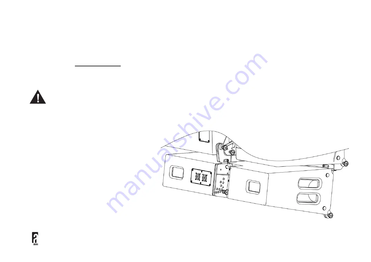
Using CNVB1824
Attach the CNVB1824 frame to the LR24 front couplers (2) and
bottom connection pin (8). Make the angle adjustments on the
LR18 modules. Lower the LR24 array onto the top LR18 module
on the Pre rig. You can, of course, also mount individual LR18
modules to the LR24 array. Mount the LR18 front couplers to
the inside points of the CNVB1824 and pin it. Take out the LR18
angle arm and mount it to the rear mounting point of the
CNVB1824 and pin with the red pin through the slot of the angle
arm. Raise the LR24 array and make the necessary cable
connections.


