background image

Americas

Alcoa Fastening Systems

Aerospace Products
Tucson Operations

3724 East Columbia
Tucson, AZ 85714
800‐234‐4825
520‐747‐9898
FAX: 520‐748‐2142

Alcoa Fastening Systems

Aerospace Products
Carson Operations

PO Box 5268
900 Watson Center Rd.
Carson, CA 90749
800‐421‐1459
310‐830‐8200
FAX: 310‐830‐1436

Alcoa Fastening Systems

Industrial Products
Waco Operations

PO Box 8117
8001 Imperial Drive
Waco, TX 76714‐8117
800‐388‐4825
254‐776‐2000
FAX: 254‐751‐5259

Alcoa Fastening Systems

Industrial Products
Kingston Operations

1 Corporate Drive
Kingston, NY 12401
800‐278‐4825
845‐331‐7300
FAX: 845‐334‐7333

Alcoa Fastening Systems

Industrial Products
Latin America Operations

Avenida Parque Lira. 79‐402
Tacubaya Mexico, D.F.
C.P. 11850
FAX: 525‐515‐1776
TELEX: 1173530 LUKSME

Far East

Alcoa Fastening Systems

Industrial Products
Australia Operations

14 Viewtech Place
Rowville, Victoria 
Australia  3178
03‐764‐5500
Toll Free: 008‐335‐030
FAX: 03‐764‐5510

Europe

Alcoa Fastening Systems

Industrial Products
United Kingdom Operations

Unit C, Stafford Park 7
Telford, Shropshire
England TF3 3BQ
01952‐290011
FAX: 0952‐290459

Alcoa Fastening Systems

Aerospace Products
France Operations

Clos D’Asseville
BP4
95450 Us Par Vigny
France
33‐1‐30‐27‐9500
FAX: 33‐1‐34‐66‐0600

A Global Organization

Alcoa Fastening Systems (AFS) maintains
company offices throughout the United States
and Canada, with subsidiary offices in many
other countries. Authorized  AFS distributors
are also located in many of the world’s 

Industrial and Aerospace centers, where they
provide a ready source of AFS fasteners,
installation tools, tool parts, and application
assistance.

For The Long Haul, The Future of Fastening
Technology, The Future of Assembly Technology,
The Future of Tooling Technology, and Tools of
Productivity are service marks of Huck
International. Huck provides technical assistance
regarding the use and application of Huck
fasteners and tooling.

NOTICE: The information contained in this
publication is only for general guidance with
regard to properties of the products shown

and/or the means for selecting such products,
and is not intended to create any warranty,
express, implied, or statutory; all warranties are
contained only in Huck’s written quotations,
acknowledgements, and/or purchase orders. It is
recommended that the user secure specific, up‐
to‐date data and information regarding each
application and/or use of such products.

HWB898    

1003‐5M

© 2003 Alcoa Fastening Systems

1 Corporate Drive, Kingston, NY 12401  • Tel: 800‐431‐3091 • Fax: 845‐334‐7333 •  www.alcoafasteningsystems.com

Certified to

ISO 14001:2004

Industrial

Products

Certified to

ISO 9001:2008

Industrial

Products

One Great Connection

SM

Alcoa Fastening Systems world-wide locations:

For the Long Haul

Содержание 2025 SERIES

Страница 1: ...03 15 2012 HK1006 INSTRUCTION MANUAL 2025 SERIES PNEUDRAULIC INSTALLATION TOOLS ALL MODELS ...

Страница 2: ...2025 series Tooling HK1006 Alcoa Fastening Systems 2 ...

Страница 3: ... 8 PREPARATION FOR USE 9 SERVICING THE TOOL GENERAL 9 DAILY 9 WEEKLY 9 DISASSEMBLY GENERAL 10 HEAD HANDLE 11 PINTAIL BOTTLE VACUUM SYSTEM 11 12 ASSEMBLY HEAD HANDLE 12 13 GENERAL 13 PINTAIL BOTTLE VACUUM SYSTEM 13 FILL AND BLEED 14 MEASURING TOOL STROKE 15 ASSEMBLY DRAWINGS 16 17 PARTS LIST 18 19 TROUBLESHOOTING ACCESSORIES 20 C CONTENTS ONTENTS ...

Страница 4: ...ener ejecting may occur 17 Where applicable always clear spent pintail out of nose assembly before installing the next fastener 18 There is possibility of forcible ejection of pintails or spent mandrels from front of tool 19 Check clearance between trigger and work piece to ensure there is no pinch point when tool is activated Remote triggers are available for hydraulic tooling if pinch point is u...

Страница 5: ...OPERATING TEMPERATURE 125 F 52 C POWER SOURCE 90psi MAX shop air HYDRAULIC FLUID ATF meeting DEXRON III DEXRON IV MERCON Allison C 4 or equivalent specifications Fire resistant hydraulic fluid may also be used and is required to comply with OSHA regulation 1926 302 paragraph d the fluid used in hydraulic power tools shall be fire resistant fluid approved under schedule 30 of the US Bureau of Mines...

Страница 6: ...psi 6 2 BAR SPEED CYCLES 30 per minute MAX OPERATING TEMPERATURE 125 F 52 C POWER SOURCE 90psi MAX shop air HYDRAULIC FLUID ATF meeting DEXRON III DEXRON IV MERCON Allison C 4 or equivalent specifications Fire resistant hydraulic fluid may also be used and is required to comply with OSHA regulation 1926 302 paragraph d the fluid used in hydraulic power tools shall be fire resistant fluid approved ...

Страница 7: ...si 6 2 BAR SPEED CYCLES 30 per minute MAX OPERATING TEMPERATURE 125 F 52 C POWER SOURCE 90psi MAX shop air HYDRAULIC FLUID ATF meeting DEXRON III DEXRON IV MERCON Allison C 4 or equivalent specifications Fire resistant hydraulic fluid may also be used and is required to comply with OSHA regulation 1926 302 paragraph d the fluid used in hydraulic power tools shall be fire resistant fluid approved u...

Страница 8: ...ttle valve and out the bottom of the tool As the hydraulic rod moves upward a column of fluid is forced into the head which moves the pull piston back The attached nose assembly moves with the pull piston to start fastener installation When fastener installation is completed the trigger is released Air pressure with the assistance of a spring causes the throttle valve to return to its up position ...

Страница 9: ...oblems will keep tool operating efficiently and prevent downtime The tool should be serviced by personnel who are thoroughly familiar with how it operates 2 A clean well lighted area should be available for servicing the tool Special care must be taken to prevent contamination of pneumatic and hydraulic systems 3 Proper hand tools both standard and special must be available 4 All parts must be han...

Страница 10: ...rom end cap Remove Spring 49 from Throttle Valve Fig 14 7 Tap Cylinder Head 45 down with soft mallet to take pressure off ring and remove Retaining Ring 38 Fig 2 8 Screw Button Head Screws 40 back into Cylinder Head Carefully pry on screws to remove head Remove O ring 46 9 Remove air piston from cylinder by pulling on Lock Nut 43 with vise grips Remove Piston Quad Ring 47 10 Remove Bumper 34 from ...

Страница 11: ... out with punch Remove Dowel Pin 3 to disconnect cable from trigger PINTAIL BOTTLE VACUUM SYSTEM 2025V 2025LV Figures 5 6 15 NOTE The following steps are for the disassembly of the 2025V and 2025LV models only Please use these steps in conjunction with the General and Head Handle disassembly sections of this manual 1 By reaching through the window of Pintail Bottle 24 remove Retaining Ring 62 and ...

Страница 12: ...hread Piston Assembly Tool 123111 2 for 2025 2025B 2025V or 123111 4 for 2025L 2025LB 2025LV onto Piston 6 Slide complete Gland Assembly and Wiper Seal 9 onto Piston 6 7 Install assembled components in gently from rear of tool using a press as shown in Fig 8 8 Remove Piston Assembly Tool 123111 2 or 123111 4 and POLYSEAL Insertion removal 121694 2025 Tool 9 Install Rear Wiper Seal 23 into End Cap ...

Страница 13: ... install Pivot Screw 48 in cylinder to retain throttle arm 53 24 2025 2025L Push Pintail Deflector 24 onto End Cap 21 2025B 2025LB Position Adapter 64 and Pintail Bottle 24 on End Cap and by reaching through the window of the Pintail Bottle install Washer 63 and Retaining Ring 62 Figures 14 15 2025V 2025LV See DISASSEMBLY OF PINTAIL BOTTLE AND VACUUM SYSTEM Procedure 25 Tool is now completely asse...

Страница 14: ...n fill port install bleed plug and tighten Step 7 Connect airline to tool and measure the tools stroke refer to the Measuring Tool Stroke section If stroke is less than specified remove bleed plug and top off fluid Reinstall bleed plug and recheck stroke Step 8 Increase air pressure to specifications Install two fasteners to check function and installation in a single stroke or cycle tool with sta...

Страница 15: ... Figure 12 Figure 13 2025 2025B 2025S 2025V Step 1 Cycle Piston all the way forward and measure X Step 2 Cycle and hold piston back and measure Y Step 3 Stroke Y X 2025L 2025LB 2025SL 2025LV Step 1 Cycle Piston all the way forward and measure X Step 2 Cycle and hold piston back and measure Y Step 3 Stroke X Y ...

Страница 16: ...36 37 38 39 40 41 42 43 44 45 46 47 48 SECTION A A 6 HUCK INTL INC 1 CORP DR KINGSTON N Y 12401 USA SCFM L M GPM BAR PSI 61 60 59 M A X PRESS FLOW HUCK 2025 S N 74 HUCK INTL INC 1 CORP DR KINGSTON N Y 12401 USA SCFM L M GPM BAR PSI 61 60 59 M A X PRESS FLOW HUCK 2025 S N 49 50 51 50 52 53 C C 51 Swivel Assembly 57 SECTION C C 58 74 25 Gland Assembly 26 27 28 29 30 31 32 33 2024 2024L style Timing ...

Страница 17: ...25 series Tooling HK1006 Alcoa Fastening Systems 17 54 A A 21 70 22 68 69 23 67 66 65 64 63 62 71 PARTIAL SECTION AA 24 6 FIG 15 A ASSEMBLY SSEMBLY D DRAWING RAWING Refer to Parts Lists on following pages ...

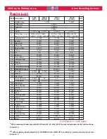
Страница 18: ... 590240 1 590240 1 590240 1 1 21 End Cap 125739 127030 125863 125739 1 22 Washer 507323 507323 507323 1 23 Wiper Seal 507351 507351 507351 1 24 Pintail Deflector 124210 n a n a 124210 1 Pintail Bottle n a 123772 123772 n a 1 25 Gland Assy 125742 125742 125742 1 26 Gland Housing 125740 125740 125740 1 27 O Ring 500787 500787 500787 1 28 Polyseal 507447 507447 507447 1 29 Spacer 125741 125741 125741...

Страница 19: ... 56 O Ring 1 57 O Ring 500779 500779 500779 2 58 O Ring 500778 500778 500778 1 59 CE Sticker 590350 590350 590350 1 60 Max Pressure Flow Sticker 590351 590351 590351 1 61 HUCK Address Sticker 590347 590347 590347 1 62 Retaining Ring n a n a 501007 n a 1 63 Washer n a n a 506628 n a 1 64 Adapter n a n a 123784 n a 1 65 O Ring n a n a 500790 n a 1 66 Retaining Nut n a n a 502317 n a 1 67 Wiper Housi...

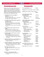
Страница 20: ...ton 6 a Worn or damaged piston Polyseal 18 replace if necessary 6 Hydraulic fluid leaks at front of Pull Piston 6 a Worn or damaged Front Gland 15 inspect Polyseal 14 O ring 12 and Back up Ring 11 Replace if necessary 7 Pull Piston 6 will not return a Throttle Valve 52 stuck Lubricate O rings 50 b Throttle Arm 53 Cable 2 or Trigger 5 binding 8 Air leaks at air Cylinder Head 45 a Worn or damaged O ...

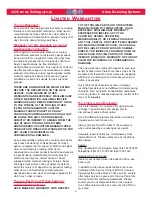
Страница 21: ... day warranty period for tooling other items nonstandard or custom products described above and Huck shall inspect products for which such claim is made TOOLING PART S AND OTHER ITEMS NOT MANUFACTURED BY HUCK HUCK MAKES NO WARRANTY WITH RESPECT TO THE TOOLING PART S OR OTHER ITEMS MANUFACTURED BY THIRD PARTIES HUCK EXPRESSLY DISCLAIMS ANY WARRANTY EXPRESSED OR IMPLIED AS TO THE CONDITION DESIGN OP...

Страница 22: ...rganization Alcoa Fastening Systems AFS maintains company offices throughout the United States and Canada with subsidiary offices in many other countries Authorized AFS distributors are also located in many of the world s Industrial and Aerospace centers where they provide a ready source of AFS fasteners installation tools tool parts and application assistance For The Long Haul The Future of Faste...

Отзывы: