


68/314
3CC08991ATAA TQ BJA 01
Issue 01 -- March 2004
3.3
--
Installing the equipment
It is assumed that the installer has already installed the other peripheral equipment (cable trays, multiplexes,
etc).
3.3.1 -- Information required for installation
Appendix 2 contains a sheet for you to complete to collate all the general information needed for the installation
procedure.
3.3.2 -- Precautions concerning electromagnetic compatibility (EMC) and safety
1) Installation is designed to meet all new requirements concerning electromagnetic compatibility and safety.
2) The EMC performance of the equipment depends largely on installation practices (cable installation, earthing
connections, etc) which should be based on best trade practices.
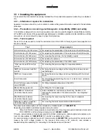
3.3.3 -- Tools required
The list of the tools required to install the microwave links of the 9400 UX family is given below (applies to all
frequency bands).
Tool
Usage examples
2.5 mm Allen key (for M3 screw)
x For adjusting the polarization of the antenna and the HSB coupler
3 mm Allen key (for M4 screw)
x For adjusting the polarization of the antenna and the HSB coupler
5 mm Allen key (for M6 screw)
x For mounting the antenna, the hot standby coupler
6 mm Allen key (for M8 screw)
x For pointing the antenna
8 mm Allen key (for M10 screw)
x For adjusting the polarization of the HSB coupler
“Pipe” wrench and 13 mm flat
wrench
For mounting the pole mounting for a separate antenna
16/17 mm box wrench and flat
wrench
x For fixing the pole mounting and fine tuning the antenna and vari-
ous fastenings
16/17 mm torque wrench
For fixing the pole mounting and various fastening with the correct
torque
5 mm flat wrench
For dismantling/reassembling the cover on classic main, extension
and access IDUs
8 mm flat torque wrench, Radiall,
code: R282320
For fitting integrated attenuators in the ODU
20 mm flat torque wrench
x For fitting the “N” coaxial plugs
3.5 x 100 mm screwdriver
(for slotted head screws)
x Indoor installations: connectors, software key, handles, or for
changing the polarization of the antenna and for “non integrated”
assembly
10 x 100 mm screwdriver
(for slotted head screws)
For mounting the “pole mounting” in the case of a separate
antenna.
Manually or with a screwdriver
(for slotted head screws)
For mounting the solar shield of ODU A9400 flat ODU
The above tools marked with an “x” are included in a “station toolkit”, ref: 9400UXT103.
Depending on installation, additional equipment may be useful:
--
“Mars Actel” OSA3 Compax insertion and extraction tool, for wiring compax terminal blocks (mars actel
IDC) COMPAX; and Sub-D plug crimping tool, ref: 608868-1 (AMP).
Of course, normal installer’s tools are essential: drill, drill bits, soldering iron, cable tie pliers, terminal pliers, etc.
A set of consumables, ref: 9400UXT002 for “one link” is available as an option.
For commissioning, an optional “service kit” (commercial code 9400UXT102) can be used: this can be used to
measure the AGC voltage (relative to the received field) using a DC voltmeter, and includes a
headset/microphone assembly for connecting to the telephone service channel*.
Содержание 9400 UX
Страница 1: ...3CC08991ATAA TQBJA 01 Alcatel 9400 UX User Manual ...
Страница 4: ...4 314 3CC08991ATAA TQ BJA 01 Issue 01 March 2004 PAGE INTENTIONALLY LEFT BLANK ...
Страница 6: ...6 314 3CC08991ATAA TQ BJA 01 Issue 01 March 2004 PAGE INTENTIONALLY LEFT BLANK ...
Страница 14: ...14 314 3CC08991ATAA TQ BJA 01 Issue 01 March 2004 PAGE INTENTIONALLY LEFT BLANK ...
Страница 19: ...19 314 3CC08991ATAA TQ BJA 01 Issue 01 March 2004 1 3 5 Eco Declaration ...


