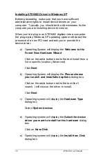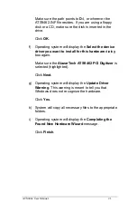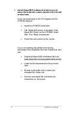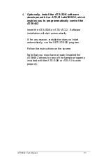
34
ATS9462 User Manual
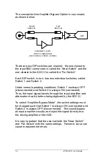
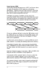
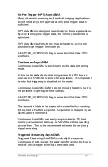
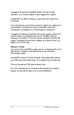
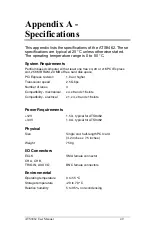
The concept behind Amplifier Bypass Option is very simple,
as shown below:
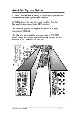
There are two DIP switches per channel: the one closest to
the input BNC connectors is called the “Near Switch” and the
one closest to the ADC IC is called the “Far Switch”.
Each DIP switch, in turn, has two individual switches, called
Switch 1 and Switch 2.
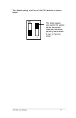
Under normal operating conditions, Switch 1 is always OFF
(disconnected) and Switch 2 is always ON (connected).
Thus, the input signal travels through the input amplifier and
attenuator circuitry before being digitized by the ADC IC.
To select “Amplifier Bypass Mode”, the switch settings must
be changed such that Switch 1 is always ON (connected) and
Switch 2 is always OFF (disconnected). This would bypass
all input amplifier circuitry and inject the signal directly into
the driving amplifier of the ADC.
It is very important that the user set both the “Near Switch”
and “Far Switch” with the same settings. Failure to do so can
cause measurement errors.
VARIABLE GAIN
INPUT AMPLIFIER
(INCLUDES ATTENUATORS)
NEAR
SWITCH
FAR
SWITCH
ADC
Содержание ATS9462
Страница 2: ......
Страница 19: ...ATS9462 User Manual 11 SyncBoard 4X for up to 4 digitizers SyncBoard 8X for up to 8 digitizers ...
Страница 62: ...54 ATS9462 User Manual ...
Страница 63: ......

