background image

© 2004 Alamo Group Inc.

Page 8 - 3

Interstater  (NH TS-100A , 115A , 125A  & 135A  Asy.   Manual) 06/04

Rear Three Point Mower
Connection:

5.

Leveling the Rear Mower & Adjust gutting

Cutting Height. The Rear Mower is leveled with the
top Three Point Link. The Cutting Height is adjusted
by moving the Roller up or down by change the
bearing bracket mounting hole. The is a decal on the
deck next the  Operators/ parts manual cannister
(See Figure 5 & 6)

6.

Rear Mower Completly Connected. With the

rear mower completly connected. Check all Oil lev-
els and grease mower components (See Figure 9)
before running mower. Also DO NOT start tractor if
the rest of the assembly to the interstater is not
done. Make certain that all hoses, compontents,
wiringing is completed and Oil Tank for interstater
has been filled with oil.

7.

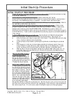
Slip clutch is incorporated in the PTO driv-

eline.  It is designed to slip, absorb the shock load,
and protect the driveline. 

It is important that the

clutch lining plates slip when an obstacle or load
heavier than clutch setting is encountered.  There-
fore, if the machine sits outside longer than 30 days
and is exposed to rain and/or humid air it is impor-
tant to make sure that the clutch lining plates are not
rusted/corroded together.  Before using the mower
use the following procedure to make sure the clutch
will slip and give the overload protection required.
(See Figure 8) This is a required step because the
driveline has been sitting and may be stuck.

A.

Loosen nuts


 on springs until the springs can

freely rotate, yet remain secure on bolts.

B.

Attach mower to tractor and start the tractor.
Set the engine speed at 1200 RPM.

C.

Mark outer plates with marker, paint or any
form that will work for you to tell if the compo
nents of the clutch slipped.

D.

Engage the PTO (approximately one sec-
ond) and then quickly disengage it.  The
friction lining plates should break loose
(check the mark).

E.

Turn tractor off and tighten the nuts on the
springs to their original position of 1-5/16"
compressed spring length.

Rear Three Point Mower

Figure 6

Figure 5

Figure 7

Содержание Interstater TS-100A, TS-115A,

Страница 1: ...onal options special equipment tractor manufacturer modifications new tractor models or Customer alterations may prevent this Mount Kit from being properly mounted to the tractor Alamo Group is not responsible for modifications to the MountKit to accommodate these differences INTERSTATER New Holland Cab or Rops Tractor TS 100A TS 115A TS 125A TS 135A INTERSTATER ...

Страница 2: ...e of accidents BEFORE YOU START Read the safety messages on the implement and shown in your manual Observe the rules of safety and common sense WARRANTY INFORMATION Read and understand the complete Warranty Statement found in this Manual Fill out the Warranty Registration Form in full and return it within 30 Days Make certain the Serial Number of the Machine is recorded on the Warranty Card and on...

Страница 3: ... HELP Make sure the call is necessary Most of the calls received may not be necessary if the Dealer Service Technician would do the following 1 Check the Service Information at your Dealership provided by Alamo Industrial This would include Service Bulletins Information Bulletins Parts Manuals Operators Manuals Assembly ManualorServiceManual manyoftheseareavailableviatheAlamoIndustrialInternetsite...

Страница 4: ...eTractor 3 3 Install Driveshaft Pumps 3 3 to 3 4 Connect Fittings Hoses To Pumps 3 4 to 3 6 Connect Hoses to Frame 3 7 to 3 9 Connect Hoses to Tank Valve 3 8 to 3 9 Install Return Pressure Gauge 3 8 Install Oil Level Sight Glass in Tank 3 8 InstallOilTemperatureGauge 3 8 Install Motor Valve Tank Return Lines 3 8 Section 4 Remote Control Cable Connections 4 1 to 4 11 Cylinder to Valve Hose Connecti...

Страница 5: ...ion 7 WingMowerInstallation 7 1 to 7 11 Wing Mower Cut Off Switches 7 1 to 7 5 Wing Mower Hose Connections 7 6 to 7 11 WiringSchematic 7 7 Pump Motor Hydraulic Schematic 7 8 to 7 11 Section 8 RearMowerInstallation 8 1 to 8 5 InitialStart UpProcedure 8 4 to 8 7 Lubricationchart 8 5 HydraulicTankFillingProcedure 8 6 Section 9 Tractor Mower Mounting Requirements 9 1 to 9 5 INDEX ASSEMBLY INSTRUCTION ...

Страница 6: ... 2004 Alamo Group Inc Page 0 4 Interstater NH TS 100A 115A 125A 135A Asy Manual 06 04 NOTES ...

Страница 7: ... 2004 Alamo Group Inc Page 1 1 Interstater NH TS 100A 115A 125A 135A Asy Manual 06 04 INTERSTATER New Holland TS100A TS115A TS125A TS135A Tractor PRE DELIVERY INSPECTION CHECKLIST Section 1 ...

Страница 8: ...ydraulic Tank mounting Pins Bolts in place correctly ___ All Welds inspected toinsure proper welds and locations Hydraulic System ___ Oil Level in Hydraulic Tank is within the sight gauge Item 5 page 1 4 ___ Hose connections are tight ___ Hoses do not have any kinks or twist in them ___ Front Pump Shaft adapter bolts are tight ___ Front Pump Shaft Coupler Drive Shaft is lubricated and has an anti ...

Страница 9: ...e is reading in the Green after Oil is warm ___ Check the function of the Mower Head On Off Valve and switch for proper function ___ Make sure that the tractor will not start with the mower on off switch in the on position ___ Check the Blade Rotation for the Rotary Mower Head to make sure it is turning Clockwise looking from the top of the mower deck ___ Make sure the control valve boom movements...

Страница 10: ... 2004 Alamo Group Inc Page 1 4 Interstater NH TS 100A 115A 125A 135A Asy Manual 06 04 Tractor Mower Component Location Check List Right Wing Flail Left Wing Flail Rear Center Flail Pumps Hyd Tank Cover ...

Страница 11: ... 2004 Alamo Group Inc Page 2 1 Interstater NH TS 100A 115A 125A 135A Asy Manual 06 04 INTERSTATER New Holland TS100A TS115A TS125A TS135A Tractor Main Frame Asy Section 2 ...

Страница 12: ...the rear of the tractor and to the frame support rails at front The Hydraulic Tube bracket tube assembly needs to be bolted to the Main frame Hydraulic Tube Assembly has a left and a right hand side the LH and RH side has to be installed as shown See Figure 2 3 If this is not bolted on correctly the hoses will not fit correctly later Mount Frame Rails To Tractor 1 Install the Frame Mounts Rails Th...

Страница 13: ...ghtening Mainframe Bolts With all the bolts installed the bolts at the front of the mainframe to the frame mounting rails the bolts through the rear of the mainframeintothetractor Tightentheboltsbeginning with the bolts that mount the frame rail mount to the tractor in the front See Figure 3 4 Second tighten the four bolts that mount the frame rail to the frame rail mounts See Figure 3 Next tighte...

Страница 14: ...e the transport lugs welded to them 7 Install the Lift and Tilt Cylinders Install the Lift cylinder and the Tilt Cylinder When installing these they must be installed with the rod end clevis grease fitting facing up and out See Figure 10 11 The CylinderfortheLeftWingwillinstallthesameastheRH side The Wing RH LH Lift Cylinders MUST have lift control spacers installed to control wing lift height See...

Страница 15: ...y and the C clips andpinsthatholdhandlestothespools SeeFigure 12 2 Bolt Valve Mounting Bracket to Mainframe The valve mounting bracket is bolted to the Right Handsideofthetractor Itisboltedtothemainframe Therearetwodifferentsetsofholeinvalvemounting bracket this allows the location of the valve to be varied 3 Install The Cylinder Control Valve to Valve Bracket The control valve is mount to the val...

Страница 16: ... 2004 Alamo Group Inc Page 2 6 Interstater NH TS 100A 115A 125A 135A Asy Manual 06 04 NOTES ...

Страница 17: ... 2004 Alamo Group Inc Section 3 1 Interstater NH TS 100A 115A 125A 135A Asy Manual 06 04 INTERSTATER New Holland TS100A TS115A TS125A TS135A Tractor Pump Driveshaft Hyd Tank Section 3 ...

Страница 18: ...Mount Plate Mounting Bolt Washer Driven Pulley Drive Belt Shield Drive Pulley Splined Sleeve Weldment Driveshaft Bearing Bearing Collar Driveshaft Pulley Adapter Locknut PulleyAdapter MountingBolts Tractor Engine Pulley Pump Mount Weldment Tandem Pump for Dual Wings Right Wing Pump Left Wing Pump Driveshaft Bearing installs into pump mount weldment here Small Cyl Hyd Pump Mount Plate mounts here F...

Страница 19: ... is seated into the inner hole of the pump mount weldmentwherethedriveshaftcomesthrough Slide thebearingcollarontodriveshaftuntilseatedagainst bearing Makingcertainthatdriveshaftisseatedinto crankshaft pulley adapter tighten setscrew for bear ing collar See Figure 1 6 InstallDrivepulley Splinedsleeveweldment Thedrivepulleyweldmentanddrivebeltwillhave to be installed at the same time If the drive b...

Страница 20: ... over tighten the belt it should be tightened to firm Holding the tension on the belt tighten the mounting bolts You may need to get someone to help you with this DO NOT over tighten the Drive Belt as it could damage the pump See Figure 6 14 Prepare Tandem Pump Fittings DO NOT remove any caps or plugs on hydraulic hoses or connections until you are connecting them this will keep dirt out The Tande...

Страница 21: ...ows there will be two small plugs screwed into tank Remove these plugs and install the pipe thread end of the two small hose after coating the threads with pipe sealer Connect the other end of the hose to the elbows on the side of the pumps NOTE Only the Tandem pump will have case drains the smaller pump used to power the hydraulic cylinder system will not use a case drain See Figure 9 11 Return T...

Страница 22: ...nd no sealer on ID of fittings The Tandem Pump Suction hoses will be sent longer thanneededandwillneedtobecuttofit SeeFigure 11 The Aux Pump Suction hose will need to be cut to fit and connected now See Figure 11 DO NOT have any kinks in the suction hose it will starve the pump of oil causing damage to system 19 Cover Pressure Hoses with Sleeving With the two pressure hoses run the hose retaining ...

Страница 23: ...the other hose is not Identified Connect these two hoses at the Main frame crossmember now See Figure 16 17 22 Connect Hoses to correct Bulkhead fittings is important here The Pressure hoses MUST be connected correctly to the correct bulkhead fitting If they are not they will damage the head cooling tubes and or other components DO NOT connect any hoses until instructed to do so Always double chec...

Страница 24: ...outhydrau lic hoses interfering with cooler 24 Install Return Filter Pressure Gauge The return filter pressure gauge screws into the side of the return filter housing This gauge is a low pres sure gauge that is marked in green and red areas See Figure 19 The Oil Pressure return gauge has arubberytipontopofit thetiptillhavetohavethetip of it cutoff Using a utility knife or suitable knife cut the ti...

Страница 25: ...urn hose to cross member and Hoses to Control Valve Connect the return hose to the cross member on right hand side of main frame crossmember See Figure 23 The other end will connect to the return filter Tee fitting See Figure 24 29 Connect Pressure Return Hose to Cylin der Control valve Connect the pressure hose run ning from the RH side of small pump to RH Top side of control valve The port will ...

Страница 26: ...Interstater NH TS 100A 115A 125A 135A Asy Manual 06 04 2004 Alamo Group Inc Section 3 10 NOTES ...

Страница 27: ... 2004 Alamo Group Inc Page 4 1 Interstater NH TS 100A 115A 125A 135A Asy Manual 06 04 Section 4 INTERSTATER New Holland TS100A TS115A TS125A TS135A Tractor Remote Control Cable Connections ...

Страница 28: ...ready on the cable screw the nut out until it is against the clip from the bottom side tightening this nut against clip will lock the other nut inside of clip See Figure 3 2 Connect Clip to Valve Spool Turn the clip and the valve spool to where the hole in the clip and theholeinthecliparealigned Usingahammerdrive the roll pin through the hole in the spool and through the other side of clip See Fig...

Страница 29: ...terstater NH TS 100A 115A 125A 135A Asy Manual 06 04 Remote Control Cable Connections Figure 4 Figure 5 Figure 6 Figure 8 Remote Control Cable Connections continued Control Valve Hoses 1 2 3 4 5 6 7 8 Figure 7 Figure 9 1 2 3 Vent Plug ...

Страница 30: ...ess together and smoothly coming up through floor Before a hole is cut in floor check the under side to make certain that the hole saw is not going to damage any of the components under the floor Make certain that the holecutisfarenoughoverthatitwillnotinterferewith operators foot room Cut hole through floor mat and floorusingaround 2 holesaw SeeFigure12 After you cut the rubber mat with the hole ...

Страница 31: ...ves to Push the Wire Harness up through the floor and boot cover See Figure 15 18 5 Insert Cables up through Boot Cover Mark the cables as to which is which on the control valve as they need to be connected in the same order on the inside of the cab as they are connected to the control valve See Figure 17 Remote Control Cable Connections Cab Tractor continued Wire Harness Control cable Cable Cover...

Страница 32: ...ee Figure 20 3 Attach Control Valve to the Valve Stand Attach Control Valve to the Valve Stand with 2 3 8 x 1 bolts 2 3 8 locknuts Attach the Top Cover and the Bottom Cover to the Valve Mount Bracket with 8 3 8 x 1 bolts 8 3 8 washers and 8 3 8 locknuts See Figure 21 4 Install Mower Wing ON Off Switches Make certain to install connector so that larger brown wires are located on bottom poles of swi...

Страница 33: ... adjustment at the valve end may be required too ensure that the spool returns to neutralwhenthecontrollerisintheneutralposition See Figure 25 10 The control lever assemblies utilizes a small springtomakeupforfreeplayinthecabletovalve connection The control valve spool spring pro vides the centering capabilities of the controller and the valve spool Lack of centering at the controller is normally ...

Страница 34: ...s to allow the handles to be rotated to position the handles straight up See Figures 11 26 27 Cab Model Shown 13 TieCablesandWireHarnesstogether Tie the cables and Wire Harness together with plastic ties inside the cab and outside the cab This will keep them from moving around Cab Mdel Shown 14 Control Valve Hydraulic Schematic The schematic shows the routing of hoses to the cylinder control valve...

Страница 35: ...ning nut on the Valve end of the cable is tightened Tighten these retaining nuts now See Figure 28 16 CheckHydraulicHoseRouting Shown below is the routing of the hydraulic Cylinder Control Valve Double check these before running Unit See Figure 29 Remote Control Cable Connections Cable Retaining Nuts Qty 4 12 12 12 12 1 1 1 1 1 1 RH Wing Lift Cylinder RH Wing Tilt Cylinder KH Wing Tilt Cylinder LH...

Страница 36: ...e been in stalled is tied up and out of the way of folding components or any thing that may damage them See Figure 31 32 3 Wires from the safety switch must be routed close to cutterhousing sidesheet and lift frame pivot points This will prevent wires from being stretched and broken when cutterhousing is raised or lowered to maxi mum positons NOTE Route wires in such a manner to prevent interferen...

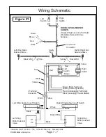
Страница 37: ...HOWN Single Wings have only the Right Wing Motor Solenoid Valve harness 1 2 1 2 Right Wing Motor Solenoid Valve Left Wing Motor Solenoid Valve Right Wing Safety Cut off Switch Left Wing Safety Cut off Switch Black Black White Black Yellow White White Yellow Red Brown Red Yellow Right Switch Left Switch Fuse 3 Terminal Connector White B W White Black Brown Start Terminal Brown Starter Solenoid Red ...

Страница 38: ... 2004 Alamo Group Inc Page 4 12 Interstater NH TS 100A 115A 125A 135A Asy Manual 06 04 NOTES ...

Страница 39: ... 2004 Alamo Group Inc Page 5 1 Interstater NH TS 100A 115A 125A 135A Asy Manual 06 04 Section 5 INTERSTATER New Holland TS100A TS115A TS125A TS135A Tractor Tractor Exhaust Modification ...

Страница 40: ...rner of the cab that supports the exhaust pipe This bracket will be removed also See Figure 2 Lay the Bracket and exhaust pipe aside as the kit will include replace Pipe Bracket and Fasteners 4 Exhaust Relocation Kit The new Exhaust pipe mount bracket clamp and flange mounting bolt will be included in Exhaust Relocation Kit P N 02980916 Part No Qty Description 02980933 1 Exhaust Brkt Wldmnt 029809...

Страница 41: ...shown in Figure 6 if it is not already Muffler should now be 8 1 2 inward from the stock loca tion this is a must for clearance of the Wing when folded in the up Transport position Note figure 6 show a high frame installed this is for reference only the muffler should be modified before frame and boom are mounted 8 Muffler Clearance Make certain that the hoses wiringandothercomponentsarenottouch i...

Страница 42: ... 2004 Alamo Group Inc Page 5 4 Interstater NH TS 100A 115A 125A 135A Asy Manual 06 04 NOTES ...

Страница 43: ... 2004 Alamo Group Inc Page 6 1 Interstater NH TS 100A 115A 125A 135A Asy Manual 06 04 Section 6 INTERSTATER New Holland TS100A TS115A TS125A TS135A Tractor Tractor Fuel Tank Replacement ...

Страница 44: ... Figure 1 2 Remove the fuel sending unit from the factory tank The factory fuel sending unit for the fuel level gauge will be reused it will bolt into the replacement tank with out any modifications See Figure 3 Note the replacement tank will come to youallreadypaintedbutitmayrequiretouchingup after mounting 3 Install New Fuel Tank The replacement fuel tank will install with the new straps supplie...

Страница 45: ... 2004 Alamo Group Inc Page 7 1 Interstater NH TS 100A 115A 125A 135A Asy Manual 06 04 Section 7 INTERSTATER New Holland TS100A TS115A TS125A TS135A Tractor Wing Mower Installation ...

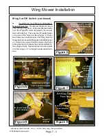
Страница 46: ...LH Bracket Shown Note there are two sets of mounting holes In figure 5 the set that have the bolts through them is used to shut wing off at 45 degree up If the other set of holes are used wing mower will shut off at 90 degrees up The 45 degree setting is recommended for standard ap plications 3 Install Switch Brackets Head Mounting Brackets Use a hoist to lift the Wing Mower and positionitformount...

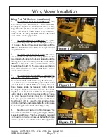
Страница 47: ...the Hinge Pin which is bolted to the mower deck at the factory There are two Threaded holes in the end of the hinge pin See Figure 7 These two holes serve dual purpose First they hole the hingebracketonandtheMagneticActivatorBracket on Some times you will need to loosen the Hinge pintoalignthetwoholessothebracketwillbolton See Figure 8 9 Tighten the two mounting bolts in to the hinge pin The Hinge...

Страница 48: ... wire harness will be run down and under the round bar of lift frame Leave harness here for now 8 Install Magnetic Switch Pickup Bracket as well as the rear hinge bracket The Rear hinge Bracket will install similar to the way the front does but not the same because the Magnetic switches and brackets bolt on with it Before installing the rear Hinge bracket locate the magnetic Switch Bracket See Fig...

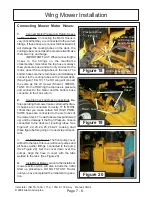
Страница 49: ... so you will have room for the cylinder mounting pin to be installed See Figure 16 When connecting the cylinder the grease fitting on the rodendmustfaceup thelockingcollaronthecylinder must face up and be tightened on rod end The RH Wing and the LH Wing will mount the same Install the RH wing the same as the LH wing Reinstall Belt Guard 11 Install Wire Harness to Motor Solenoid The thumbnutontopof...

Страница 50: ...m hose connects to the Tank return 2 Double Check all Hose Connections Be fore operating the mower make certain all hydrau lic hoses are connected correctly IT IS MOST critical that you make certain NO HIGH PRES SURE hoses are connected to the wet tubes of the mower deck The wet tubes will expand swell up and be damage if the High Pressure hose is connected to the deck wet cooling tubes See Figure...

Страница 51: ...UBLE WING MOWER SHOWN Single Wings have only the Right Wing Motor Solenoid Valve harness 1 2 1 2 Right Wing Motor Solenoid Valve Left Wing Motor Solenoid Valve Right Wing Safety Cut off Switch Left Wing Safety Cut off Switch Black Black White Black Yellow White White Yellow Red Brown Red Yellow Right Switch Left Switch Fuse 3 Terminal Connector White B W White Black Brown Start Terminal Brown Star...

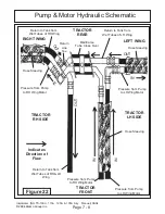
Страница 52: ...g Motor Return to Tank from Wet Tubes of LH Wing Pressure from Pump to LH Wing Motor Mainframe Tube Cross Over Pressure from Pump to RH Wing Motor Pressure from Pump to LH Wing Motor Return to Tank from Wet Tubes of RH LH Wing Hose Sleeving Hose Sleeving Hose Sleeving Return Line Tee TRACTOR RH SIDE TRACTOR LH SIDE TRACTOR FRONT TRACTOR REAR Indicates Direction of Flow IN IN IN IN O U T OUT O U T ...

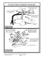
Страница 53: ...otor to Rear Wet Tube and on to Tank Case Drain from Motor to Motor Valve NEVER CONNECT HIGH PRESSURE HOSE TO WET TUBES ON DECK Figure 23 Tandem Pump RH Wing Pump Case Drain LH Wing Pump Case Drain LH Wing Pump Suction Line RH Wing Pump Suction Line RH Wing Pump High Pressure Line LH Wing Pump High Pressure Line Hose Sleeving Cyl System Supply Pump Suction Hose Tandem Pump Inner Pump for RH Wing O...

Страница 54: ... Valve to Tank Tank Return Filter Assembly Tank Return Pressure Gauge Oil Level Sight Glass Oil Temperature Gauge Figure 25 Lower Connection Always from Deck Wet Tubes to Filter Tank Return Line LOW PRESSURE Upper Connection Always from Pump To Wing Motors NEVER TO WET TUBES HIGH PRESSURE Main Frame Cross Over Bracket Tubes RH Side Shown note Tee Fitting in lower fittings Nut on Bulkhead Fittings ...

Страница 55: ...ic Schematic over hose which allows the oil to cross from the rear tube to the front tube The Tubes and the cross over hose are in the oil return to tank circuit which has to be low pressure Figure 27 Wings have a front and a rear wet tube for cooling the oil At the outer end of the decks there is a cross ...

Страница 56: ... 2004 Alamo Group Inc Page 7 12 Interstater NH TS 100A 115A 125A 135A Asy Manual 06 04 NOTES ...

Страница 57: ... 2004 Alamo Group Inc Page 8 1 Interstater NH TS 100A 115A 125A 135A Asy Manual 06 04 Section 8 INTERSTATER New Holland TS100A TS115A TS125A TS135A Tractor Rear Mower Installation ...

Страница 58: ... lower arms to 3 ConnectUpperHitchPin Theupperhitchpin willconnecttothetopthreepoint adjustableLinkwith a pin and click pin The Top Link is furnished with the tractornotwiththemower The TopLinkisadjustable in length and is used to level the mower See Figure 3 4 ConnectDriveline TheDrivelinearrivetiedto the mower See Figure 1 4 Cut the ties loose from mower Connect the clutch end of the driveline t...

Страница 59: ...portant that the clutch lining plates slip when an obstacle or load heavier than clutch setting is encountered There fore if the machine sits outside longer than 30 days and is exposed to rain and or humid air it is impor tant to make sure that the clutch lining plates are not rusted corroded together Before using the mower use the following procedure to make sure the clutch will slip and give the...

Страница 60: ...NEVER be adjusted to the point where the springs are com pressed solid Minimum spring length is 1 1 8 The slip clutch should be checked periodically and adjusted to compensate for wear The lining plates are 1 8 thick when new Replace after 1 32 wear If the mower has been idle for an extended period of time or in wet weather before operat ing check to be sure the friction lining plates are not froz...

Страница 61: ...ints LUBRICATE ALL POINTS BEFORE OPERATING MOWER FIRST TIME A Lift Frame Pivot Pin B Wing Mower Belt Idler Arm C Cuttershaft Bearings D TIlt Cylinder Rod Ends E Lift Cylinder Rod Ends F Roller Bearings G Rear Mower Idler Arm H Banjo Bearings J Banjo Coupling K Driveline Yoke L Driveline slip Figure 9 ...

Страница 62: ...ll tilt the tank and allow only a minimum amount of air when filling B Avoid hydraulic contamination by filtering the hydraulic oil while filling the hydraulic tank C Filter buggies or carts are commercially available for hydraulic system clean up These consist of a high efficiency high capacity filter a circulating pump a drive motor and hoses for connecting the overhauled machine s hydraulic sys...

Страница 63: ...n this speed for about 5 minutes Check complete INTERSTATER look for any leaks loose connections or anything that could cause premature wear or failure FINAL CHECK Run INTERSTATER for about 1 2 hour at full speed Check for leaks and vibrations Frequently check oil temperature Make certain it does not exceed 180 deg NOTE When raising wings make certain there is no interference with mower frame cyli...

Страница 64: ... 2004 Alamo Group Inc Page 8 8 Interstater NH TS 100A 115A 125A 135A Asy Manual 06 04 NOTES ...

Страница 65: ... 2004 Alamo Group Inc Page 9 1 Interstater NH TS 100A 115A 125A 135A Asy Manual 06 04 Section 9 INTERSTATER New Holland TS100A TS115A TS125A TS135A Tractor Mounting Specifications Mount Kit Numbers ...

Страница 66: ...with a 96 centered rear head Right hand only models can be ordered with a 96 centered or 88 offset right 8 5 rear head Two lift chains are recommended for centered heads while offset heads should only be ordered with one 5 The mainframe should allow approximately 10 3 4 of ground clearance with the maximum tire size listed above 6 As with most dual wing Interstaters the left wing must be lowered f...

Страница 67: ...a 96 centered rear head Right hand only models can be ordered with a 96 centered or 88 offset right 8 5 rear head Two lift chains are recommended for centered heads while offset heads should only be ordered with one 5 The mainframe should allow approximately 10 3 4 of ground clearance with the maximum tire size listed above 6 As with most dual wing Interstaters the left wing must be lowered for in...

Страница 68: ...the battery can still be accessed and even removed with the assistance of one additional person Notice The special order kits will include a battery relocation bracket See Figure 1 however it was designed for use with 18 4 30 rear tires only Hence the dealer customer is responsible for any necessary modifications 3 For dual wing mowers the factory installed fuel tank must be replaced with the one ...

Страница 69: ...anyproblem Keepin mindthatuntilaTS125Aor135AismountedatourSeguin facility any necessary driveline modifications must be made at the dealer customer s expense 11 The dual wing component crate for tractor hydraulics includes hoses and fittings for coupling to the rear tractor hydraulic remotes Note the tractor must be equipped with four remotes Continued From Previous Page Tractor Mower Mounting Spe...

Страница 70: ... 2004 Alamo Group Inc Page 9 6 Interstater NH TS 100A 115A 125A 135A Asy Manual 06 04 NOTES ...

Страница 71: ......

Страница 72: ...Insterstater Assembly Manual New Holland TS 100A 115A 125A 135A 2004 Edition P N 02981188 iInterstater NH TS 100A 115A 125A 135A Asy Manual 06 04 2004 Alamo Group Inc ...

Отзывы: