Akytec SPK207 Скачать руководство пользователя страница 15


Service Menu 


 akYtec GmbH · Vahrenwalder Str. 269 A · 30179 Hannover · Germany · Tel.: +49 (0) 511 16 59 672-0 · www.akytec.de  


14 

Password change (see 7.2.4)


– 

Additional 

Additional features (see 7.2.5)


– 

Exit 

Return to the main screen


– 

Reboot


Exit the configuration dialog and reboot the PLC 

Changes to parameter take effect immediately without confirmation. 

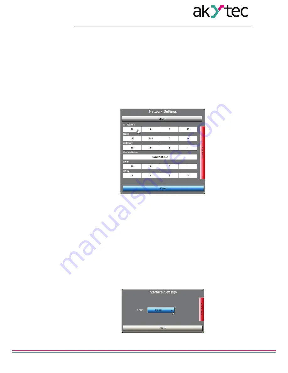
7.2.1  Network Settings 

The IP address, the SubnetMask and the standard gateway can be set. 

Use the 

Setup

 key to change the parameters. The following mask appears: 


Fig. 7.4   Input mask "Network Settings"


–  If DHCP is disabled, the PLC uses a static IP address. The IP address, the Subnet-

Mask and the standard gateway must be defined. If DHCP is enabled (green 

DHCP


key), a DHCP server will assign IP address automatically. 

–  In the field 

Device Name

 the PLC name can be changed. The name will be used by 

CODESYS after network scan. Enter the name using numerals, Latin letters and un-

derscore only. 

–  The 

DNS

 field can be used to enter domain names instead of IP addresses. 

–  Use 

Close

 key to exit the dialog. 

–  Use 

RESET

 key to apply the factory settings (see 7.3). 

7.2.2  Interface Settings 

The serial ports COM2 and COM3 can be used as RS232 and RS485 interfaces. 

Use the 

Setup

 key to change the interface. The following screen appears: 


Fig. 7.5   Input mask "Interface Settings" 

Содержание SPK207

Страница 1: ...GmbH Vahrenwalder Str 269 A 30179 Hannover Germany Tel 49 0 511 16 59 672 0 www akytec de SPK207 Control Panel User guide SPK207_2017 04_0200_EN All rights reserved Subject to technical changes and mi...

Страница 2: ...use 8 4 Installation 9 4 1 Requirements 9 4 2 Mounting 9 5 Wiring 10 5 1 1 Signal lines 10 5 1 2 Ethernet 10 6 Starting 11 7 Service Menu 12 7 1 Touchscreen Calibration 12 7 2 Configuration 12 7 2 1...

Страница 3: ...03 RS232 2x RS232 RS485 configurable Software installed CS CODESYS on Linux Web Visualization WEB Integrated web visualization 1 3 Hardware RISC processor 800 MHz 128 MB dynamic memory RAM 128 MB per...

Страница 4: ...n pointed object of max 3 mm The interface USB Host and SD slot can be used as a terminal for various Mass Storage Devices The interface of the serial port COM2 depends on the device model Table 2 2 T...

Страница 5: ...tput Fig 1 3 SPK207 right side 1 3 4 Touchscreen The touchscreen detects a finger touch or a touch with a stylus not included in package NOTICE The resistive touchscreen can be damaged by pointed or s...

Страница 6: ...delivered with a calibrated touchscreen In case of malfunction the touchscreen can be recalibrated see 6 1 1 3 5 Battery The battery is located on the motherboard Switch off the device loose four scre...

Страница 7: ...24 24 18 32 V DC Power consumption power on 20 W operation 15 W SPK207 230 230 90 264 V AC 50 47 63 Hz Power consumption power on 40 VA operation 20 VA Interfaces Basic USB Host USB Device Ethernet 1...

Страница 8: ...conditions The device is designed for natural convection cooling that should be taken into account when choosing the installation site The following environment conditions must be met clean dry and c...

Страница 9: ...indicates a potentially harmful situation which if not avoided may result in dam age of the product itself or of adjacent objects 3 1 Intended use The device has been designed and built solely for the...

Страница 10: ...cutout is required The mounting enclosure must provide a clean dry and controlled environment The seal contact surface must be clean and smooth so that the protection IP64 can be provided The mountin...

Страница 11: ...ock see Table B 1 Functional grounding is required to meet EMC level im munity NOTICE The device is not provided with an On Off switch If the external switch is not installed the device will start up...

Страница 12: ...ar Fig 6 1 Start screen Then the most important parameters can be set and the basic functions of the device can be used For the detailed description of the service menu see sec 6 If you don t touch th...

Страница 13: ...USB mass storage device CALIBRATE TOUCH SCREEN Touchscreen calibration see 7 1 SPK SETUP Access to configuration menu Network parameters COM interfaces date time password and other important parameter...

Страница 14: ...r Fig 7 3 Fig 7 2 Configuration Mode Main Screen Fig 7 3 Configuration Mode SPK207 In these dialog network and serial interfaces parameters date and time can be set and the password can be changed The...

Страница 15: ...is disabled the PLC uses a static IP address The IP address the Subnet Mask and the standard gateway must be defined If DHCP is enabled green DHCP key a DHCP server will assign IP address automaticall...

Страница 16: ...ort COM1 COM2 COM3 Number 2 3 4 7 2 3 Date and Time Use the Setup key for setting the real time clock The following screen appears Fig 7 6 Input mask Date and Time Use the on screen NumPad that appear...

Страница 17: ...e con nected USB mass storage device and SD card The memory devices are scanned every 10 seconds Remove Safely remove mass storage device The function is available when a mass storage device is connec...

Страница 18: ...u select Online Create Boot Application in the menu to create a boot application for PLC select a folder on the PC drive in the pop up dialog box Save As to save the boot application copy the content...

Страница 19: ...g of the housing and terminal blocks from dust dirt and debris checking the fastening of the device checking the wiring connecting leads fastenings mechanical damage The device should be cleaned with...

Страница 20: ...vides optimum protection If the device is not taken immediately after delivery into operation it must be carefully stored at a protected location The device should not be stored in an atmosphere with...

Страница 21: ...269 A 30179 Hannover Germany Tel 49 0 511 16 59 672 0 www akytec de 20 10 Scope of delivery SPK207 1 Fasteners and screws Set 1 3 pole plug in screw terminal block 3 Ethernet Patch cable 1 Short guide...

Страница 22: ...imensions akYtec GmbH Vahrenwalder Str 269 A 30179 Hannover Germany Tel 49 0 511 16 59 672 0 www akytec de 21 Appendix A Dimensions Fig A 1 Dimensions Fig A 2 Mounting cutout 228 152 SD 59 5 40 133 80...

Страница 23: ...nnector Pin number Signal USB A Host 1 5 V 2 Data 3 Data 4 GND USB B Device 1 5 V 2 Data 3 Data 4 GND Debug RJ12 1 TXD 2 RXD 3 not used 4 not used 5 not used 6 GND LAN Ethernet RJ45 1 Etx 2 not used 3...

Страница 24: ...Str 269 A 30179 Hannover Germany Tel 49 0 511 16 59 672 0 www akytec de 23 Table B 2 Pin assignment COM2 COM3 Pin number COM2 COM3 RS485 COM2 COM3 RS232 RJ45 COM2 COM3 RS485 RJ45 1 Data A 2 Data B RTS...

Страница 25: ...ject and double click Device in the Device tree Select the sub dialog Communication settings in the device editor and define the local Gateway Server if no gateway is defined Fig C 1 Sub dialog Commun...

Страница 26: ...269 A 30179 Hannover Germany Tel 49 0 511 16 59 672 0 www akytec de 25 Fig C 3 Correct connection to PLC Select Online Login to transfer the application to the PLC In the following dialog Fig C 4 clic...

Отзывы: