3 Setting Up
Important!
3.2.4 Connecting Microphones
Note:
Refer to fig. 9.
3.3 Connecting to Power
Important!
Refer to fig. 10.
Refer to fig. 11.
Important!
Note:
Note:
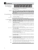
1. Use a CS MK cable of suitable length to connect the DELEGATE UNITS LINE 1 connector on the Base
Unit to one of the two connectors on the first Microphone Station.
2. Connect the other connector on the first Microphone Station to one of the two connectors on the next
Microphone Station and so on.
If you connect the maximum number of Microphone Stations, distribute the Microphone
Stations to LINE 1 through 4 as recommended in Table 4 above. Also, make sure the total cable
length from the Base Unit to the last Microphone Station does not exceed 330 feet (100 m). This
is the only way to ensure that all Microphone Stations will receive an adequate supply voltage
(21 VDC minimum).
1. Select the proper gooseneck and microphone capsule for each Microphone Station. For details refer
to the Discreet Acoustics Modular Series manual.
You can also use each type of Microphone Station with no microphone, as a monitoring device, e.g.,
for a secretary or stenographer.
2. Screw the microphone capsule on the gooseneck.
3. Screw the gooseneck into the microphone jack on the Microphone Station.
Check that the AC mains voltage stated on your power supplies is identical to the AC mains
voltage available where you will use your system. Using the power supplies with a different AC
mains voltage may cause damage to the unit.
A If you connected not more than 30 to 40 Microphone Stations to your Base Unit you will need a
single CS PS 20 power supply.
1. Open the 4-pin Phoenix connector (1) on the DC cable of the power supply and check that the jump-
er (2) between "0V1" and "0V2" as well as the jumper (2) between "+1" and "+2" are in place. These
two jumpers (2) must be in place for all Microphone Station lines (LINE 1 through LINE 4) to be
powered.
2. Connect the DC cable of the power supply to the 4-pin DC INPUT connector (3) on the Base Unit rear
panel.
3. Connect the power supply to a convenient power outlet.
B If you connected between 40 and 80 Microphone Stations to the Base Unit you will need two
CS PS 20 power supplies.
1. Remove the two jumpers (2) from the Phoenix connector (1) of one of your power supplies.
2. Disconnect the Phoenix connector from the DC cable of the second power supply and connect the
DC cable of the second power supply to the screw terminals "0V2" and "+2" on the Phoenix
connector of the first power supply.
3. Connect the Phoenix connector with the DC cables of the two power supplies to the 4-pin DC INPUT
connector (3) on the Base Unit rear panel.
4 Connect the power supplies to a convenient power outlet.
C If you connected between 80 and 200 Microphone Stations to the Base Unit you will need one
CS PS 100 power supply.
1. Install the power supply in your rack.
To ensure proper ventilation for cooling the power supply, leave one rack space each above and
below the power supply unoccupied.
2. Connect the DC cable of the power supply to the DC INPUT connector on the Base Unit rear panel.
3. Connect the power supply to a convenient power outlet.
The CS PS 20 power supply has no power switch and will use energy even when the system is switch-
ed off. We therefore recommend connecting these power supplies to a power circuit with an on/off
switch. You can use this on/off switch as a master switch for the entire system.
The EXPANSION connectors provide no supply voltage. If you are setting up a system with several
Base Units, be sure to connect the required power supply/supplies to each Base Unit.
18
(Acceptable) / Optimum Number of Microphone Stations
Power Supplies
Total
LINE 1
LINE 2
LINE 3
LINE 4
1 x CS PS 20
40
(40) / 10
(0) / 10
(0) / 10
(0) / 10
2 x CS PS 20
80
(50) / 20
(30) / 20
(0) / 20
(0) / 20
1 x CS PS 100
200
50
50
50
50
Table 4: Maximum number and
recommended distribution of
Microphone Stations vs. power
supplies used.
Содержание CS 2
Страница 62: ...Notizen Notes Notes Note Notas Notas 62 ...
Страница 63: ...63 ...
Страница 64: ... X7 X9 X10 Fig 1 Fig 2 Fig 6 Fig 3 Fig 5 Fig 4 Master Slave IC AS 8 A P3 B 0V Fig 9 Fig 7 ...
Страница 65: ...B Fig 9 Fig 7 Fig 8 Fig 11 CS PS 20 1 CS PS 20 2 0V1 0V2 1 2 Fig 10 CS PS 20 0V1 0V2 1 2 Fig 13 ...
Страница 66: ......
Страница 67: ...Notizen Notes Notes Note Notas Notas 64 ...
Страница 68: ...Notizen Notes Notes Note Notas Notas 65 ...
Страница 69: ...Notizen Notes Notes Note Notas Notas 66 ...


