Three Phase and Three Phase CT Type PMSFL User Manual - 12
As mentioned
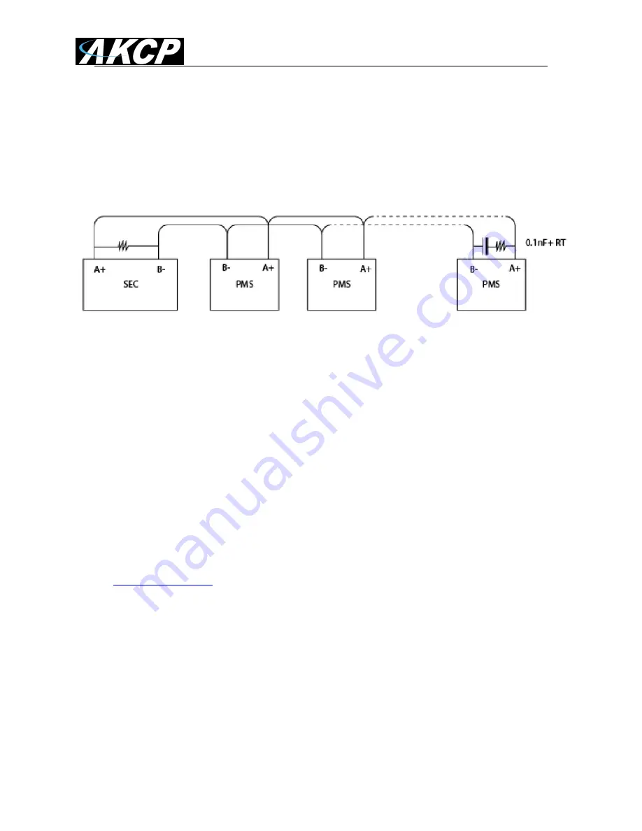
, it is possible to connect multiple PMS’s to a single securityProbe base
unit. We do not recommend connecting more than 14 Single Phase PMS to a single unit.
It is also VERY critical that you are using at least 120Ohm impedance shielded twisted
pair cable as mentioned above including the termination resisters described below.
The terminal resistors should always match the impedance of the installation cables.
As shown in the diagram above you will need to use the cable and terminal resistors in
the Modbus line as recommended by the Modbus standard. That is: a 120 Ohm
impedance cable, 120 Ohm (0.25W) termination re 0.1nF capacitor at the end of
the line.
- The SEC has a polarized line implemented
- Use the jumper aside the connector for 120 Ohm terminal resistor at the SEC side
(inside RS485 port), if the jumper is used, you must not add a terminal resistor at the
SEC side.
- If cable characteristic impedance differs from 120 Ohm, terminal resistors should match
the same impedance.
- the two ends of the cable must be connected on Line Terminations.
If you have any questions about this please consult with your engineer or contact us at
Adding each PMS to the securityProbe’s web interface
When adding the multiple PMS to the web interface in the securityProbe base unit you
have to add each PMS one at a time then change the ID from "1" to a different ID. Scan
again then change "1" to a unique ID (like PMS1, PMS2) and so on.
You will need to use the following procedures to pre-
configure the multiple PMS’s:
1. Start by connecting only one PMS, run the scan ID, set this PMS to ID 1, and then
remove this PMS both physically and from the web interface. This will hard code the


