


Product Specification of PDP Module
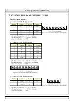
LVDS Signal and LVDS Receiver
LVDS Signal
Pin No.
Symbol
Pin No.
Symbol
Pin No.
Symbol
21
nc
nc
22
23
24
25
26
27
28
29
30
31
1
GND
11
RD-
2
RA-
12
RD+
3
RA+
13
GND
4
RB-
14
GND
5
RB+
nc
RE-
RE+
GND
DISPEN
I
2
C SDA
I
2
C SCL
nc
GND
15
nc
6
GND
16
nc
7
RC-
17
nc
8
RC+
18
nc
9
RCLK-
19
GND
10
RCLK+
20
nc
3.3V level
LG Cable, GT121-31P-TD pin number ( Top view )
1 2 3 4 5 6 7 8 9 10 111213 14 15 1617 1819 20 21 22 23 242526 27 28 29 30 31
¾
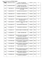
Definitions and Functions of LVDS Signal
Symbol
Definition and Function
Related Output Signal
RA
+
Channel-A Pos. Receiver Input
RA
-
Channel-A Neg. Receiver Input
R4
,
R5
,
R6
,
R7
,
R8
,
R9
,
G4
G5
,
G6
,
G7
,
G8
,
G9
,
B4
,
B5
B6
,
B7
,
B8
,
B9
,
Hsync
,
Vsync
,
BLANK
R2
,
R3
,
G2
,
G3
,
B2
,
B3,
nc
R0
,
R1
,
G0
,
G1
,
B0
,
B1,
nc
RCLK
+
Clock Pos. Receiver Input
PIX_CLK
RCLK
-
Clock Neg. Receiver Input
RB
+
Channel-B Pos. Receiver Input
RB
-
Channel-B Neg. Receiver Input
RC
+
Channel-C Pos. Receiver Input
RC
-
Channel-C Neg. Receiver Input
RD
+
Channel-D Pos. Receiver Input
RD
-
Channel-D Neg. Receiver Input
RE
+
Channel-E Pos. Receiver Input
RE
-
Channel-E Neg. Receiver Input
(P1001) : LG Cable, GT121-31P-TD
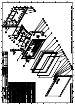
Содержание PDP4210EA1
Страница 1: ......
Страница 17: ......
Страница 18: ......
Страница 36: ...TUNER1 sch 1 Sat Mar 18 09 00 32 2006...
Страница 45: ...Keypad Remote control receiver External L R Speakers...
Страница 46: ...Remote control...
Страница 69: ......
Страница 73: ...9 The update process is successful as the progress bar is 100 After the update process is ok...