background image

45/129

Содержание LCT3285TAJ

Страница 1: ......

Страница 2: ...uit diagram 9 33 6 Basic Operation Circuit Description 34 36 7 Main IC Information 37 75 8 Panel Information 76 107 9 Explored View 108 10 Spare Pare List 109 111 11 Software Upgrade 112 129 This manual is the latest at the time of printing and does not include the modification which may be made after the printing by the constant improvement of product ...

Страница 3: ...htness The high voltage must not exceed 30 KV under any circumstances Each time when a receiver requires servicing the high voltage should be checked The reading of the high voltage is recommended to be recorded as a part of the service record It is important to use an accurate and reliable high voltage meter 2 The only source of X RAY RADIATION in this TV receiver is the picture tube For continue...

Страница 4: ... etc 6 When servicing is required observe the original lead dressing Extra precaution should be given to assure correct lead dressing in the high voltage area 7 Keep wires away from high voltage or high tempera ture components 8 Before returning the set to the customer always perform an AC leakage current check on the exposed metallic parts of the cabinet such as antennas terminals screwheads meta...

Страница 5: ... 3 129 ...

Страница 6: ... 0 12 0 12 0 0 1 3 124 1 3 5 3 6 27 8 6 27 1 7 12 60 26 9 1 7 12 2 1 7 12 3 1 4 2 4 129 ...

Страница 7: ...12 6 6 7 1 3 0 1 3 1 3 7 3 4 4 5 129 ...

Страница 8: ...pical TV System NTSC M ATSC Sound Mono Stereo SAP BTSC Sound Effect Spatial Effect and Surround Power Supply AC 120V 60Hz Power Consumption 180W Input Output Terminal Antenna Input F Type x 2 NTSC ATSC RS 232 D Sub 9 Pin Type x 1 Only for DTV VGA D Sub 15 Pin Type x 1 HDMI Ver 1 1 connector x 1 Component Video YPbPr x 2 RCA Terminals Video Input RCA Terminals x 1 S Video Input Mini Din 4 Pin Termi...

Страница 9: ...ontal Frequency kHz Vertical Frequency Hz 480i 15 734 59 94 480p 720x480 31 468 59 94 720p 1280x720 45 00 60 00 1080i 1920x1080 33 75 60 00 When the signal received by the Display exceeds the allowed range a warning message shall appear on the screen You can confirm the input signal format from the on screen Resolution Horizontal Frequency kHz Vertical Frequency Hz 480p 31 468 59 94 720p 45 00 60 0...

Страница 10: ... HDMI Receiver HDMI YPbPr1 YPbPr2 Option VGA AV S Video Audio X2 Audio X3 QS3VH257 Switch Option HEF4052 Switch WM8776 Audio ADC DAC To panel Flash 8M 16M DDR 128M DDR 128M R2S15102 Class D Amplifier POWER BOARD 5V Standby 5V 12V 9V 24VA For Class D 24V For LCD Panel Max232 Level Shift RS232 Socket Speaker LCD panel Relay Analog Tuner MAIN BOARD DTV BOARD NJRC4558 Audio Buffer Audio Output 8 129 ...

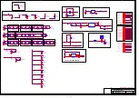
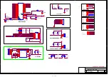
Страница 11: ...2 2 3 3 4 4 5 5 9 9 8 8 7 7 6 6 1 1 H2 HOLE GND H2 HOLE GND R637 10K R637 10K 1 2 3 4 5 6 7 8 9 10 11 J6 11x1 DIP11 P2 54 J6 11x1 DIP11 P2 54 CB2 0 1uF NC CB2 0 1uF NC CB5 0 1uF CB5 0 1uF R645 10K R645 10K 1 2 3 4 5 6 7 J23 DIP7 W H P2 54 J23 DIP7 W H P2 54 GND 1 RESET 2 VCC 3 U1 LM809 SOT 23 SMD NC U1 LM809 SOT 23 SMD NC 1 3 2 Q21 2N3904 SOT23 SMD Q21 2N3904 SOT23 SMD R15 10K NC R15 10K NC 1 3 2 ...

Страница 12: ...2 FB CE9 100uF 16v CE9 100uF 16v CE108 220uF 16v CE108 220uF 16v CE10 100uF 16v CE10 100uF 16v L4 FB L4 FB CE109 220uF 16v CE109 220uF 16v CB18 0 1uF CB18 0 1uF CE7 100uF 16v CE7 100uF 16v CE78 100uF 16v CE78 100uF 16v ADJ GND 1 OUT 2 IN 3 U11 AZ1117 3 3V SOT223 SMD U11 AZ1117 3 3V SOT223 SMD CE17 220uF 16v CE17 220uF 16v CB23 0 1uF CB23 0 1uF L49 FB NC L49 FB NC L8 FB L8 FB CE14 100uF 16v CE14 10...

Страница 13: ...et Checked MT8202E PBGA388 1 C 3 17 Thursday April 20 2006 AKAI_MT8202_27US_LVDS_V0 0 KAWA Confidential Designer Checker Title Size Document Number Rev Date Sheet Checked MT8202E PBGA388 1 C 3 17 Thursday April 20 2006 AKAI_MT8202_27US_LVDS_V0 0 KAWA Confidential Designer Checker Title Size Document Number Rev Date Sheet Checked MT8202E PBGA388 1 C 3 17 Thursday April 20 2006 AKAI_MT8202_27US_LVDS...

Страница 14: ...v C0805 SMD C49 10uF 10v C0805 SMD CE29 10uF 10V CE29 10uF 10V CB46 0 1uF CB46 0 1uF C20 1uF C20 1uF C11 4 7uF C11 4 7uF C3 10uF 10v C0805 SMD C3 10uF 10v C0805 SMD CE30 10uF 10V CE30 10uF 10V FB6 FB BEAD SMD 0603 FB6 FB BEAD SMD 0603 L3 FB L3 FB CE24 10uF 10V CE24 10uF 10V C29 0 01uF C29 0 01uF FB15 FB FB15 FB R45 49 9 1 R45 49 9 1 L13 FB L13 FB C25 4 7uF C25 4 7uF CB34 0 1uF CB34 0 1uF CE27 10uF...

Страница 15: ...130 0 1uF CB127 0 1uF CB127 0 1uF C55 3300pF C55 3300pF CB99 0 1uF CB99 0 1uF CB105 0 1uF CB105 0 1uF CB92 0 1uF CB92 0 1uF CB82 0 1uF CB82 0 1uF CB124 0 1uF CB124 0 1uF R80 22 R80 22 CE47 220uF 16v CE47 220uF 16v CB110 0 1uF CB110 0 1uF R75 75 R75 75 1 2 3 4 5 6 7 8 RN15 75x4 RN15 75x4 CB91 0 1uF CB91 0 1uF CB76 0 1uF CB76 0 1uF L16 FB L16 FB 1 2 3 4 5 6 7 8 RN24 75x4 RN24 75x4 CB125 0 1uF CB125 ...

Страница 16: ...1 IOVCC33 120 CGND18 113 IOGND33 106 QE7 114 QE6 115 QE8 111 QE5 116 QE1 123 RX1 58 RX1 59 QE9 110 WS 75 SCK 76 HSYNC 128 VSYNC 1 DE 127 CEN 2 SOG_IN 3 OSC_IN 4 NC 5 IOVCC33 7 IOGND33 6 NC 8 KWP 9 KSDA 10 CGND18 13 ODCK 119 CVCC18 12 GPIO13 16 KSCL 11 GPIO14 15 GPIO12 17 GPIO11 20 GPIO10 21 GPIO9 22 IOVCC33 19 IOGND33 18 GPIO8 23 GPIO7 26 GPIO6 27 GPIO5 28 GPIO4 29 GPIO3 32 CVCC18 24 CGND18 25 CGN...

Страница 17: ...3 1K NC R786 0 NC R786 0 NC GND 10 VCC 20 DIR 1 A0 9 A1 8 A2 7 OE 19 B7 18 A3 6 A4 5 A5 4 A6 3 A7 2 B0 11 B1 12 B2 13 B3 14 B4 15 B5 16 B6 17 U31 74LVC245A U31 74LVC245A R222 0 NC R222 0 NC R358 10k R358 10k R230 0 NC R230 0 NC R228 0 R228 0 R787 0 NC R787 0 NC CB205 0 1uF NC CB205 0 1uF NC R642 10k R642 10k GND 10 VCC 20 DIR 1 A0 9 A1 8 A2 7 OE 19 B7 18 A3 6 A4 5 A5 4 A6 3 A7 2 B0 11 B1 12 B2 13 ...

Страница 18: ...CC 16 I1C 10 YC 9 U39 QS3VH257 TSSOP16 SMD U39 QS3VH257 TSSOP16 SMD R373 100k R373 100k R443 0 NC R443 0 NC R368 10K R368 10K R627 0 NC R627 0 NC 1 2 3 4 5 6 7 8 J32 DIP8 W H P2 0 J32 DIP8 W H P2 0 L76 FB NC L76 FB NC R447 0 NC R447 0 NC 1 3 2 Q28 2N3904 SOT23 SMD NC Q28 2N3904 SOT23 SMD NC R451 0 NC R451 0 NC R440 0 NC R440 0 NC R381 100k R381 100k C158 1000pF NC C158 1000pF NC R438 0 NC R438 0 N...

Страница 19: ...L70 22 L70 22 TP54 TP54 CE126 10uF 25v CE126 10uF 25v R408 10k R408 10k 1 3 2 Q34 2N3906 Q34 2N3906 R409 10k R409 10k R750 100 R750 100 CB194 0 1uF CB194 0 1uF CE150 10uF 25V CE150 10uF 25V R246 10K NC R246 10K NC C184 100pF C184 100pF R653 10K R653 10K TP53 TP53 CB115 100pF NC CB115 100pF NC CE125 10uF 25v CE125 10uF 25v CB133 33pF NC CB133 33pF NC CB134 33pF NC CB134 33pF NC R655 100 R655 100 CE...

Страница 20: ...DS_V0 0 1 C 10 17 Thursday April 13 2006 AUDIO VIDEO IN CIRCUIT KAWA Confidential Designer Checker Title Size Document Number Rev Date Sheet Checked AKAI_MT8202_27US_LVDS_V0 0 1 C 10 17 Thursday April 13 2006 AUDIO VIDEO IN CIRCUIT KAWA Confidential Designer Checker TO MT8202 FROM AV BOARD FROM Tuner THIS PAGE NEARLY IC C110 47nF C110 47nF C135 330pF C135 330pF C148 100nF C148 100nF C122 100nF C12...

Страница 21: ...F C641 0 1uF R159 47K R159 47K C642 0 1uF C642 0 1uF 1 3 2 D69 DIODE SMD BAV99 D69 DIODE SMD BAV99 1 3 2 D71 DIODE SMD BAV99 D71 DIODE SMD BAV99 C639 0 1uF C639 0 1uF C638 0 1uF C638 0 1uF R138 68 R138 68 R738 0 R738 0 C87 10nF C87 10nF C88 5pF C88 5pF R154 2K R154 2K R333 510 R333 510 R132 68 R132 68 C168 NC C168 NC C89 10nF C89 10nF C167 NC C167 NC C90 4 7nF C90 4 7nF C100 5pF C100 5pF R134 100 ...

Страница 22: ...C R102 0 NC R102 0 NC R99 10K NC R99 10K NC R93 4 7k NC R93 4 7k NC CE95 220uF 16v NC CE95 220uF 16v NC R18 10K NC R18 10K NC 1 2 3 4 5 6 7 8 9 10 11 12 13 14 15 16 17 18 19 20 21 22 23 24 25 26 27 28 29 30 J10 FI SE30P HF LVDS 30P P1 25 S J10 FI SE30P HF LVDS 30P P1 25 S R27 0 NC R27 0 NC R108 0 R108 0 L56 FB NC L56 FB NC R287 4 7k NC R287 4 7k NC R112 10K R112 10K R33 4 7k R33 4 7k R100 0 NC R10...

Страница 23: ...D KAWA Confidential Designer Checker BACK LIGHT CIRCUIT KEYPAD ADC KEY GPIO KEY KEYPAD C99 1000pF C99 1000pF 1 3 2 Q32 2N3904 SOT23 SMD Q32 2N3904 SOT23 SMD R389 10K R389 10K 1 3 2 Q17 2N3904 NC Q17 2N3904 NC C39 1000pF C39 1000pF R754 10k NC R754 10k NC C52 1000pF C52 1000pF C124 1000pF C124 1000pF R305 10k NC R305 10k NC C53 1000pF C53 1000pF R384 10K R384 10K R111 10K R111 10K L58 FB L58 FB 1 2...

Страница 24: ...2 GND3 23 GND4 24 AF MPX 14 VS_IF 13 NC 1 BT 2 AFC 7 NC 8 TU1 FQ1236 MK3 TU1 FQ1236 MK3 C646 10nF C646 10nF R422 1 8K R422 1 8K C649 820pF C649 820pF CE630 220uF 16V CE630 220uF 16V CB243 0 1uF CB243 0 1uF R180 0 NC R180 0 NC CB239 0 1uF CB239 0 1uF FB21 47 FB21 47 CE635 220uF 10V CE635 220uF 10V CE625 470uF 16V CE625 470uF 16V R419 220 R419 220 R420 10 R420 10 FB14 BEAD SMD 1206 NC FB14 BEAD SMD ...

Страница 25: ...01 1 8uH R133 75 R133 75 C58 47pF C58 47pF C60 47pF C60 47pF C105 220pF C105 220pF C170 47pF NC C170 47pF NC L96 1 8uH L96 1 8uH 1 3 2 D102 DIODE SMD BAV99 D102 DIODE SMD BAV99 FB27 0 FB27 0 L103 0 L103 0 R169 47K R169 47K R167 0 R167 0 R114 56 R114 56 FB32 0 FB32 0 R258 NC R258 NC C104 220pF C104 220pF R261 1 5K R261 1 5K 1 2 3 4 5 6 K1 K2 R W W R P12 RCA2X2 AV4 8 4 13P R W W R P12 RCA2X2 AV4 8 4...

Страница 26: ...STAL GPIO PWM0 DIMMING GPIO PWM1 BACKLIGHT ON OFF SDA1 TO MT5351 I F REQUEST GPIO1 NO USE SCL1 TO MT5351 I F READY CCIR_V 0 3 KEYPAD DE GPIO DVD IR VCLK KEPAD CH F_A21 KEYPAD LED RED ADCIN4 FOR TUNER AFC ADCIN0 KEYPAD GPIO8 SPEAKER SWITCH GPIO10 Indicates active video at HDMI port GPIO0 PDP USE CCIR_V4 PDP USE CCIR_CLK PDP USE ADCIN3 PDP 5VD DETECT R241 100 R241 100 R772 100 R772 100 CE97 10uF 25V...

Страница 27: ...260 NC D65 SR260 NC CE166 1000uF 35v CE166 1000uF 35v R238 0 NC R238 0 NC R783 0 R783 0 R758 0 NC R758 0 NC L117 0 L117 0 CE161 2 2uF 50v CE161 2 2uF 50v R155 0 R155 0 3 1 2 4 L21 ACM3225 102 2P L2 5X3 5 L21 ACM3225 102 2P L2 5X3 5 R297 1 5K NC R297 1 5K NC R782 0 R782 0 R188 47K R188 47K R781 0 R781 0 C668 0 047uF C668 0 047uF CE159 3 3uF 50v CE159 3 3uF 50v R239 0 NC R239 0 NC R780 0 R780 0 C674...

Страница 28: ...GNAL 01 INDEX AND INTERFACE 02 POWER 03 TUNER 04 MT5111 ASIC 05 MT5351 ASIC 06 MT5351 PERIPHERAL 07 DDR MEMORY 08 NOR FLASH JTAG UART GND GROUND GROUND MT5111 MT5351 REFERENCE DESIGN 4 LAYERS MT5351RA V2 NS NON STUFF DIGITAL VIDEO OUTPUT UART RS232 DIGITAL AUDIO INTERFACE SPDIF CIRCUIT RA V2 ADDED AUDIO SWITCH REFINE POWER CIRCUIT 2005 07 14 POWER INPUT FROM MAIN BOARD DIGITAL OUTPUT 3 3V RN3 33x4...

Страница 29: ...OUT 2 IN 3 L4 FB BEAD SMD 0805 CE6 220uF 16v C220UF16V D6H11 U6 AZ1117 adj SOT223 SMD ADJ GND 1 OUT 2 IN 3 CB9 0 1uF C0603 SMD U4 AZ1117 adj SOT223 SMD ADJ GND 1 OUT 2 IN 3 U2 AZ1117 adj SOT223 SMD ADJ GND 1 OUT 2 IN 3 CE16 220uF 16v C220UF16V D6H11 CB6 0 1uF C0603 SMD CB146 0 1uF NC C0603 SMD L33 FB CPL 0302 U21 MP2105 NC IN 4 GND 2 EN 1 SW 3 FB 5 L6 FB BEAD SMD 0805 U3 AP1084 TO220 DIP 5V TO220 ...

Страница 30: ...B BEAD SMD 0805 CB18 0 1uF C0603 SMD C7 1uF C0603 SMD L12 NS L IND SMD 0805 CE18 10uF 16v C10UF16V D5H11 R22 510 1 R0603 SMD R17 NS R0603 SMD R21 510 1 R0603 SMD R18 100 R0603 SMD R16 10K R0603 SMD U9 PORT SAW FILTER X6965D SIP5K SIP5K DIP IN 1 IN 2 GND 3 OUT 5 OUT 4 CE17 10uF 16v C10UF16V D5H11 U8 PORT TUNER TD1336 FGHP GND TH1 GND TH2 GND TH3 GND TH4 Outdoor PS 1 VS_splitter_ 5V 2 OOB_OP 3 NC 4 ...

Страница 31: ...F C0603 SMD CB38 0 1uF C0603 SMD CB36 0 1uF C0603 SMD R31 4 7K R0603 SMD C13 1uF C0603 SMD QF2 2N7002 N MOSFET 2 1 3 RN12 33x4 RN0603 SMD 1 2 3 4 5 6 7 8 CB32 0 1uF C0603 SMD CB24 0 1uF C0603 SMD C11 1uF C0603 SMD CB23 0 1uF C0603 SMD RN13 33x4 RN0603 SMD 1 2 3 4 5 6 7 8 R32 4 7K R0603 SMD CB30 0 1uF C0603 SMD R34 10 R0603 SMD FB6 FB BEAD SMD 0603 CB22 0 1uF C0603 SMD QF1 2N7002 N MOSFET 2 1 3 CB3...

Страница 32: ...1 D4 APLLCAP0 E4 AGND L11 AGND L12 AGND L13 AGND M11 AGND M12 AGND M13 AGND N11 AGND N12 AGND N13 PDD0 A27 PDD1 B26 PDD2 A26 PDD3 C25 PDD4 B25 PDD5 A25 PDD6 D24 PDD7 C24 PDCD1 A28 CVDD M5 CVDD N5 CVDD U5 CVDD E10 CVDD E19 CVDD M24 CVDD N24 CVDD U24 CVDD AE14 CVDD AE15 IOVDD P5 IOVDD R1 IOVDD R2 IOVDD R3 IOVDD R4 IOVDD R5 IOVDD T5 IOVDD E11 IOVDD E12 IOVDD E13 IOVDD E14 IOVDD E15 IOVDD E16 IOVDD E1...

Страница 33: ...B50 4 7uF C0805 SMD CB72 0 1uF C0603 SMD R44 NS 10 R0603 SMD CB75 0 1uF C0603 SMD C29 10uF 10v C0805 SMD C104 0 1uF C0603 SMD X1 VCXO FR270003 OSC 6P SMD 7X5 CVIN 1 TRI STATE 2 GND 3 OUT 4 NC 5 VDD 6 C184 0 1uF C0603 SMD JP1 JP2 DIP P2 54 2x1 1 2 R38 NS 10M R0603 SMD C128 0 1uF C0603 SMD CB67 0 1uF C0603 SMD CB57 4 7uF C0805 SMD R40 NS 50 R0603 SMD CB71 0 1uF C0603 SMD R39 NS 10 R0603 SMD C25 1500...

Страница 34: ... R69 47 C170 0 1uF C0603 SMD RN14 22x4 1 2 3 4 5 6 7 8 R76 75 C109 0 1uF C0603 SMD R107 100 R0603 SMD U18 16M x 16 DDR TSOP 66 TSOP_0D65_22D6LX9D7W_66SP VDD 1 DQ0 2 VDDQ 3 DQ1 4 DQ2 5 VSSQ 6 DQ3 7 DQ4 8 VDDQ 9 DQ5 10 DQ6 11 VSSQ 12 DQ7 13 NC 14 VDDQ 15 LDQS 16 NC 17 VDD 18 NC 19 LDM 20 WE 21 CAS 22 RAS 23 CS 24 NC 25 BS0 26 BS1 27 A10 AP 28 A0 29 A1 30 A2 31 A3 32 VDD 33 VSS 34 A4 35 A5 36 A6 37 A...

Страница 35: ...K R0603 SMD C32 NS 10pF C0603 SMD CB152 0 1uF J3 10x2 DIP10X2 W H IDE P2 54 1 3 5 7 9 11 13 15 17 19 2 4 6 8 10 12 14 16 18 20 R97 0 R0603 SMD R98 4 7K R0603 SMD R83 NS 4 7K R0603 SMD CB153 0 1uF U22 MAX3232 R1IN 13 R2IN 8 T1IN 11 T2IN 10 C 1 C1 3 C2 4 C2 5 V 2 V 6 R1OUT 12 R2OUT 9 T1OUT 14 T2OUT 7 VCC 16 GND 15 R84 0 R0603 SMD D3 SOT23 SMD 1 3 2 J6 CON8 1 2 3 4 5 6 7 8 P2 CONNECTOR DB9 5 9 4 8 3 ...

Страница 36: ...ing 3 pcs Extension PCB 1 pcs Timming controller board and 1 pcs Back Light board in the Module SET There are 6 pcs PCBs including 1 pcs ATV Tuner board 1 pcs keypad board 1 pcs Remote Control Receiver board 2 pcs L R Speakers and 1 pcs Main Video board 1 pcs ATSC board in the SET 34 129 ...

Страница 37: ... HDMI signals and D SUB signals to digital ones and to transmit to Control board 3 Control board Dealing with the digital signal for output to panel 4 Extension board Output addressing signals 5 ATV Tuner Board To convert TV RF signal to video and SIF audio signal to Main board 6 ATSC Board Receiver and converter ATSC TV signal to transmit to main board 35 129 ...

Страница 38: ...ce Make sure status Mute Internal External speaker c No picture but with signals output OSD and back light d Abnormal noise on screen 3 POWER NO picture no power output 4 Back Light a No picture b Flash on screen c Darker picture with signals 5 ATV Tuner a No ATV Noise b No ATV signals 6 ATSC a No ATSC TV signal 36 129 ...

Страница 39: ... ARM 926EJ with 16K I Cache and 16K D Cache It can support 64Mb to 1Gb DDR DRAM devices with configurable 32 64 bit data bus interface MT8202 MT8202G is a highly integrated Single Chip for LCD TV supporting video input and output format up to HDTV It includes 3D comb filter TV decoder to retrieve the best image from popular composite signals MT8293 HDMI PanelLink Cinema Receiver R2S15102NP Digital...

Страница 40: ...38 129 ...

Страница 41: ...39 129 ...

Страница 42: ...40 129 ...

Страница 43: ...41 129 ...

Страница 44: ...42 129 ...

Страница 45: ...43 129 ...

Страница 46: ...44 129 ...

Страница 47: ...45 129 ...

Страница 48: ...46 129 ...

Страница 49: ...47 129 ...

Страница 50: ...48 129 ...

Страница 51: ...49 129 ...

Страница 52: ...50 129 ...

Страница 53: ...51 129 ...

Страница 54: ...52 129 ...

Страница 55: ...53 129 ...

Страница 56: ...54 129 ...

Страница 57: ...55 129 ...

Страница 58: ...56 129 ...

Страница 59: ...57 129 ...

Страница 60: ...58 129 ...

Страница 61: ...59 129 ...

Страница 62: ...60 129 ...

Страница 63: ...61 129 ...

Страница 64: ...62 129 ...

Страница 65: ...mode 20Wx1ch VD 18V at 8 Ω The RENESAS original circuits realize high power efficiency low noise and low distortion characteristics Pop sound Less Built in protection function Over Current Over Temperature and Under Voltage Built in Mute and Stand by function 3 Operating Condition Recommanded Power supply voltage from 11V to 25V Recommanded Speaker Impedance from 4 to 8Ω Fig 1 Package 20pin QFN Bo...

Страница 66: ...L 13 PWM input pin 2 for phase compensation SE operation Protection Timer pin At protection mode the output becomes L level The timing capacitor is connected Capacitor connection pin for analog block reference voltage source GND pin for analog block Control pin for PWM carrier frequency A capacitor is connected so that it may not be influenced of power supply change Ripple Filter Analog input 1 Th...

Страница 67: ...g on PCB printed circuit board Size 75mm x 75mm 2 5W Without External Heat Sink 1 Double PCB copper planes t 0 035mm are needed and each size is almost 75mm X 75mm θja 30 W 4layer PCB Pd 6 3W With Infinite Heat Sink the ideal condition θjc 12 W 1 6W 1 0W Without External Heat Sink 2 There is no copper plane and no thermal treatment 1layer PCB 0 Under Development 10 4W 4 2W Ta 75 150 25 NOTE PCB pa...

Страница 68: ...rmal via PCB size estimation 10Wx2ch 75mm x 75mm The exposed die pad is directly soldered with the printed circuit board pattern GND plane PCB Power plane the economy design 2 layer PCB Thermal Via Rich GND Power line Area Additional Thermal Via PCB The GND Power line total area size is also equal to the above GND Power line total area size of the 4layer PCB PCB size estimation 10Wx2ch 75 α mm x 7...

Страница 69: ...TL at SE dB 80 TBD Mute Attenuation Mute dB 50 TBD dVD 100mVrms f 100 Hz Ripple Rejection Ratio PSRR W 20 TBD THD 10 VD 18V RL 8Ω at BTL at SE 93 TBD Po 10 10W Power Efficiency Eff uVrm D s TB 100 A Weighted filter Output Noise level No W ch 10 TBD THD 10 VD 24V RL 8Ω Maximum output power Pomax TBD 0 1 Po 1W Total Harmonic Distortion THD A 6 Output over current Protection Current IPR 120 Thermal S...

Страница 70: ...000u 0 047u R for GND 150k R for GND 47k R for GND 47k 15uH Vz 27 30V Vz 27 30V Exposed Die Pad STBYL ROSC OUT1 HB1 VD1 VS1 IN1 MUTEL CBIAS AVDD OUT2 VD2 VS2 PROT HB2 DVDD IN2 GND 3 4 2 5 1 9 8 7 10 6 14 15 11 12 13 16 17 18 20 19 PWM2 PWM1 47k 10k 0 47u 22k 8Ω R2S15102 10u 0 1u 0 1u 3p 150k 150k 3p STANDBY 47k 0 1u 0 1u 0 1u 1000u 0 047u R for GND 150k 15uH Vz 27 30V Vz 27 30V Fig 5 BTL operation...

Страница 71: ...1 12 13 16 17 18 20 19 PWM2 PWM1 47k 10k 0 47u 10u 22k 8Ω R2S15102 10u 0 1u 0 1u 3p 150k 150k 3p STANDBY 47k 0 1u 0 1u 0 1u 1000u 0 047u R for GND 150k Vz 27 30V FB FB If this speaker lines is very short the LPF coil is not needed PWM Output BTL note It may be need the input Pre LPF Exposed Die Pad Exposed Die Pad 0 1u 1u note R for GND s are for the evaluation only and not needed actually note Th...

Страница 72: ...70 129 ...

Страница 73: ...71 129 ...

Страница 74: ...72 129 ...

Страница 75: ...73 129 ...

Страница 76: ...74 129 ...

Страница 77: ...75 129 ...

Страница 78: ...proval Specification MODEL NO V320B1 L01 LCD TV Head Division TVHD PDD QRA Dept DDIII DDII DDI Approval Approval Approval Approval LCD TV Marketing and Product Management Division Customer Approved by Note 76 129 ...

Страница 79: ...R CHARACTERISTICS 3 2 3 INVERTER INTERFACE CHARACTERISTICS 4 BLOCK DIAGRAM 4 1 TFT LCD MODULE 5 INTERFACE PIN CONNECTION 5 1 TFT LCD MODULE 5 2 BACKLIGHT UNIT 5 3 INVERTER UNIT 5 4 BLOCK DIAGRAM OF INTERFACE 5 5 LVDS INTERFACE 5 6 COLOR DATA INPUT ASSIGNMENT 6 INTERFACE TIMING 6 1 INPUT SIGNAL TIMING SPECIFICATIONS 6 2 POWER ON OFF SEQUENCE 7 OPTICAL CHARACTERISTICS 7 1 TEST CONDITIONS 7 2 OPTICAL...

Страница 80: ...18 0 621 0 648 0 651 0 678 0 681 Gx 0 242 0 239 0 272 0 269 0 302 0 299 Gy 0 576 0 567 0 606 0 597 0 636 0 627 By 0 044 0 036 0 074 0 066 0 104 0 096 The Drawing is modified The Drawing is modified Contrast Ratio 800 1 1000 1 Weight Min 5900 5700 Typ 6100 5900 Max 6300 6100 Rush Current Max 1 7 3 CNF1 Connector Pin Assignment Pin3 is modified LVDS INTERFACE is modified Contrast Ratio Min 600 800 T...

Страница 81: ...eader Pin No Symbol Description 5 NC Æ GND NC Æ Ground LVDS INTERFACE Revised Notes 1 RSVD reserved pins on the transmitter shall be H or L or OPEN INPUT SIGNAL TIMING SPECIFICATIONS Add LVDS Receiver Clock Input cycle to cycle jitter max 200 ps PACKING METHOD Modify Figures 9 1 and 9 2 PACKING METHOD Modify Figures 9 2 79 129 ...

Страница 82: ...function option Color Reproduction Nature color 1 3 APPLICATION TFT LCD TVs 1 4 GENERAL SPECIFICATI0NS Item Specification Unit Note Active Area 708 954 H x 398 592 V 32 02 diagonal mm Bezel Opening Area 714 96 H x 404 6 V mm 1 Driver Element a si TFT active matrix Pixel Number 1366 x R G B x 768 pixel Pixel Pitch Sub Pixel 0 1730 H x 0 5190 V mm Pixel Arrangement RGB vertical stripe Display Colors...

Страница 83: ... of display area is less than or equal to 60 ºC with LCD module alone in a temperature controlled chamber Thermal management should be considered in final product design to prevent the surface temperature of display area from being over 60 ºC The range of operating temperature may degrade in case of improper thermal management in final product design Note 3 11 ms half sine wave 1 time for X Y Z No...

Страница 84: ...MS Power Supply Voltage VBL 0 30 V 1 Control Signal Level 0 3 7 V 1 3 Note 1 Permanent damage to the device may occur if maximum values are exceeded Functional operation should be restricted to the conditions described under normal operating conditions Note 2 No moisture condensation or freezing Note 3 The control signals includes Backlight On Off Control Internal PWM Control External PWM Control ...

Страница 85: ... 100 mV Differential Input Low Threshold Voltage VLVTL 100 mV Common Input Voltage VLVC 1 125 1 25 1 375 V LVDS Interface Terminating Resistor RT 100 ohm Input High Threshold Voltage VIH 2 7 3 3 V CMOS interface Input Low Threshold Voltage VIL 0 0 7 V Note 1 The module should be always operated within above ranges Note 2 Measurement Conditions Vcc rising time is 470us 470us 5V GND 0 9Vcc 0 1Vcc R1...

Страница 86: ...CTERISTICS Ta 25 2 ºC Value Parameter Symbol Min Typ Max Unit Note Lamp Voltage VW 1280 VRMS IL 4 5mA Lamp Current IL 4 0 4 5 5 0 mARMS 1 2450 VRMS 2 Ta 0 ºC Lamp Starting Voltage VS 2360 VRMS 2 Ta 25 ºC Operating Frequency FO 40 70 KHz 3 Lamp Life Time LBL 50 000 60 000 Hrs 4 Active Area c Vertical Stripe Pattern R R R R R R R R G G G G B B B B B B G G G G B B B B R R Active Area Active Area a Wh...

Страница 87: ...uce interference with horizontal synchronous frequency of the display input signals and it may result in line flow on the display In order to avoid interference the lamp frequency should be detached from the horizontal synchronous frequency and its harmonics as far as possible Note 4 The life time of a lamp is defined as when the brightness is larger than 50 of its original value and the effective...

Страница 88: ...ation 3 2 3 INVERTER INTERFACE CHARACTERISTICS Value Parameter Symbol Test Condition Min Typ Max Unit Note ON 2 0 5 0 V On Off Control Voltage OFF VBLON 0 0 8 V HI 2 0 5 0 V Internal External PWM Select Voltage LO VSEL 0 0 8 V MAX 3 0 V minimum duty ratio Internal PWM Control Voltage MIN VIPWM VSEL L 0 V maximum duty ratio HI 2 0 5 0 V duty on External PWM Control Voltage LO VEPWM VSEL H 0 0 8 V d...

Страница 89: ...Tf Backlight on duration 0 VEPWM 3 0V VIPWM TPWMR VW Ext Dimming Function Int Dimming Function Ton Minimun Duty 100 External PWM Duty VBL VBLON VSEL 0 0 0 0 2 0V 0 8V 2 0V 0 8V TPWMF Toff External PWM Period 87 129 ...

Страница 90: ...ECTOR JAE FI X30SSL HF or equal GND Vcc FRAME BUFFER RX0 RX1 RX2 RX3 RXCLK TIMING CONTROLLER BACKLIGHT UNIT INVERTER CONNECTOR CN1 S10B PH SM3 TB D LF JST or equal CN2 S12B PH SM3 TB D LF JST or equal CN3 CN10 SM02 8 0 B BHS 1 TB LF JST or equal VBL GND CN2 CN11 S2B ZR SM3A TF D LF JST or equal GND SEL E_PWM I_PWM BLON VBL CN1 88 129 ...

Страница 91: ...xel 3 18 RX3 Positive transmission data of pixel 3 19 GND Ground 20 GND Ground 21 GND Ground 22 GND Ground 23 GND Ground 24 GND Ground 25 GND Ground 26 VCC Power supply 5V 27 VCC Power supply 5V 28 VCC Power supply 5V 29 VCC Power supply 5V 30 VCC Power supply 5V Note 1 Connector Part No FI X30SSL HF JAE or compatible Note 2 Reserved for internal use Left it open Note 3 Low or open normal display ...

Страница 92: ...HS 1 TB LF CN11 Housing ZHR 2 JST or equivalent Pin No Symbol Description Wire Color 1 LV Low Voltage Black 2 LV Low Voltage White Note 2 The backlight interface housing and return cable for low voltage side is a model ZHR 2 manufactured by JST or equivalent The mating header on inverter part number is S2B ZR SM3A TF D LF or equivalent 2 HV White 1 HV Pink 2 HV White 1 HV Pink Retruen cable 1 LV W...

Страница 93: ...M control signal E_PWM should be connected to low when internal PWM was selected SEL low 11 I_PWM Internal PWM control signal I_PWM should be connected to ground when external PWM was selected SEL high 12 BLON Backlight on off control CN3 CN10 Header SM02 8 0 B BHS 1 TB LF JST or equivalent Pin No Symbol Description 1 CCFL HOT CCFL high voltage 2 CCFL HOT CCFL high voltage CN11 Header S2B ZR SM3A ...

Страница 94: ...pedance shall be 50 ohms per signal line or about 100 ohms per twist pair line when it is used differentially R0 R7 G0 G7 B0 B7 DE Host Graphics Controller TxIN PLL PLL R0 R7 G0 G7 B0 B7 DE DCLK Timing Controller LVDS Transmitter THC63LVDM83A LVDF83A LVDS Receiver THC63LVDF84A Rx0 Rx0 Rx1 Rx1 Rx2 Rx2 CLK CLK RxOUT 51Ω 51Ω 51Ω 51Ω 51Ω 51Ω 51Ω 51Ω 51Ω 51Ω 100pF 100pF 100pF 100pF 100pF Rx3 Rx3 92 129...

Страница 95: ... OUT0 TA OUT0 TA OUT1 TA OUT1 TA OUT2 TA OUT2 TA OUT3 TA OUT3 Rx 0 Rx 0 Rx 1 Rx 1 Rx 2 Rx 2 Rx 3 Rx 3 27 29 30 32 33 35 37 38 39 43 45 46 47 51 53 54 55 1 6 7 34 41 42 49 50 2 3 5 Rx OUT0 Rx OUT1 Rx OUT2 Rx OUT3 Rx OUT4 Rx OUT6 Rx OUT7 Rx OUT8 Rx OUT9 Rx OUT12 Rx OUT13 Rx OUT14 Rx OUT15 Rx OUT18 Rx OUT19 Rx OUT20 Rx OUT21 Rx OUT22 Rx OUT26 Rx OUT27 Rx OUT5 Rx OUT10 Rx OUT11 Rx OUT16 Rx OUT17 Rx OU...

Страница 96: ... 255 0 0 0 1 1 1 0 0 0 1 1 1 0 0 0 1 1 1 0 0 0 1 1 1 0 0 0 1 1 1 0 0 0 1 1 1 0 0 1 0 1 1 0 1 0 1 0 1 0 0 0 0 0 0 0 0 0 0 0 0 0 0 0 0 0 0 0 0 0 0 0 0 0 0 0 0 0 0 0 0 0 0 0 0 0 0 0 0 0 0 0 0 0 0 0 0 0 0 0 0 0 0 0 0 0 0 0 0 0 0 0 0 0 0 0 0 0 0 0 0 0 0 0 0 0 0 0 0 0 0 0 0 0 0 0 0 0 0 0 0 0 0 0 0 Gray Scale Of Green Green 0 Dark Green 1 Green 2 Green 253 Green 254 Green 255 0 0 0 0 0 0 0 0 0 0 0 0 0 0 ...

Страница 97: ...3 Hz Frame Rate Fr6 57 60 63 Hz 2 Total Tv 778 795 888 Th Tv Tvd Tvb Display Tvd 768 768 768 Th Vertical Active Display Term Blank Tvb 10 27 120 Th Total Th 1436 1798 1936 Tc Th Thd Thb Display Thd 1366 1366 1366 Tc Horizontal Active Display Term Blank Thb 70 432 570 Tc Note 1 Since this module is operated in DE only mode Hsync and Vsync input signals should be set to low logic level Otherwise thi...

Страница 98: ...LVDS RECEIVER INTERFACE TIMING DIAGRAM RXCLK RXn 14 1T 14 3T 14 5T 14 7T 14 9T 14 11 T 14 13T Tlvsu Tlvhd Tc 96 129 ...

Страница 99: ...ernal system for the module input should follow the definition of Vcc Note 2 Apply the lamp voltage within the LCD operation range When the backlight turns on before the LCD operation or the LCD turns off before the backlight turns off the display may momentarily become abnormal screen Note 3 In case of Vcc is in off level please keep the level of input signals on the low or high impedance Note 4 ...

Страница 100: ... described in 7 1 and stable environment shown in Note 6 Item Symbol Condition Min Typ Max Unit Note Contrast Ratio CR 800 1000 2 Response Time Gray to gray average 8 12 ms 3 Center Luminance of White LC 450 550 cd m 2 Average Luminance of White LAVE 400 450 cd m 2 4 White Variation δW 1 3 7 Cross Talk CT 4 0 5 Rx 0 622 0 652 0 682 Red Ry 0 302 0 332 0 362 Gx 0 240 0 270 0 300 Green Gy 0 559 0 589...

Страница 101: ...atio CR L255 L0 L255 Luminance of gray level 255 L 0 Luminance of gray level 0 CR CR 5 CR X is corresponding to the Contrast Ratio of the point X at the figure in Note 8 Note 3 Definition of Gray to Gray Switching Time 12 o clock direction θy 90º 6 o clock θy 90º θx θx θy θy x y y x Normal θx θy 0º θX 90º θX 90º Optical Response 100 90 10 0 Gray to gray switching time Time Gray to gray switching t...

Страница 102: ...E L 1 L 2 L 3 L 4 L 5 5 L x is corresponding to the luminance of the point X at the figure in Note 8 Note 5 Definition of Cross Talk CT CT YB YA YA 100 Where YA Luminance of measured location without gray level 0 pattern cd m 2 YB Luminance of measured location with gray level 0 pattern cd m 2 Active Area YA U D 2 W 8 YA R 7D 8 W 2 YA D D 2 7W 8 YA L D 8 W 2 0 0 D W Gray 128 Active Area Gray 0 D 4...

Страница 103: ...ting Backlight for 1 hour in a windless room Note 7 Definition of White Variation δW Measure the luminance of gray level 255 at 5 points δW Maximum L 1 L 2 L 3 L 4 L 5 Minimum L 1 L 2 L 3 L 4 L 5 D W Active Area Vertical Line Horizontal Line Test Point X 1 to 5 5 1 2 3 4 D 4 D 2 3D 4 W 4 W 2 3W 4 X LCD Module LCD Panel Center of the Screen Display Color Analyzer Minolta CA210 Light Shield Room Amb...

Страница 104: ...X X X Y M D L N N N N Serial ID includes the information as below a Manufactured Date Year 0 9 for 2000 2009 Month 1 9 A C for Jan Dec Day 1 9 A Y for 1 st to 31 st exclude I O and U b Revision Code Cover all the change c Serial No Manufacturing sequence of product d Product Line 1 Line1 2 Line 2 etc Product Line Year Month Date CMO Internal Use CMO Internal Use Revision CMO Internal Use Serial No...

Страница 105: ... H 3 Weight approximately 28Kg 4 modules per box 9 2 PACKING METHOD Figures 9 1 and 9 2 are the packing method Approx 28Kg 4 modules per carton Carton dimensions 906 L x384 W x580 H mm Weight LCD TV Module Anti static Bag Carton Carton Label PE Foam Bottom 2 pcs Drier Figure 9 1 packing method 103 129 ...

Страница 106: ...Figure 9 2 Packing method 104 129 ...

Страница 107: ...easily scratched 8 Moisture can easily penetrate into LCD module and may cause the damage during operation 9 High temperature or humidity may deteriorate the performance of LCD module Please store LCD modules in the specified storage conditions 10 When ambient temperature is lower than 10ºC the display quality might be reduced For example the response time will become slow and the starting voltage...

Страница 108: ...11 MECHANICAL CHARACTERISTICS 奇美電子股份有限公司 CHI MEI 106 129 ...

Страница 109: ...奇美電子股份有限公司 CHI MEI 107 129 ...

Страница 110: ...108 129 ...

Страница 111: ... ASS Y MT5111CE W O MAX3232 1 000000 SET K 7 200 L32AD21 01AA FRONT CABINET SILVER BLACK 32 LCT32AD 1 000000 Piece S 8 202 L32AD32 01AA BACK CABINET BLACK W O DVD 1 000000 Piece S 9 206 L32AD01 01R SPK CABINET BACK BLACK 1 000000 Piece S 10 269 42SD01 01L REMOTE RECEIVE LENS 1 000000 Piece S 11 277 L32AD11 01S FUNCTION KEY SIL MATERIAL BLACK LCT32SD 1 000000 Piece S 12 300 L32AD06 02C POLYFOAM LEF...

Страница 112: ...2AD01 03AP MODEL LABEL LCT3285TA AKAI 1 000000 Piece S 29 563 119 SERIAL NO LABEL 1 000000 Piece S 30 568 P46T02 02 WARNING LB ENG 42SF NIL 1 000000 Piece S 31 578 L32AD01 01AP FUNCTION SHEET FOR LCT3285TA MT8202 P 1 000000 Piece S 32 579 42D102 09 SERIAL NO BAR CODE LABEL 42D1 1 000000 Piece S 33 579 42D105 01 PROTECTIVE EARTH LABEL FOR ESA 42TD1 1 000000 Piece S 34 579 L27AD09 01 CAUTION LABEL E...

Страница 113: ...WIRE ASSY P2 5 7P 7P L400MM 5V STANBY POWER MT8202 FOR 27 32 LCD 1 000000 Piece S 47 E3461 064043 WIRE ASSY P2 0 12P 3P2 0 8P2 5 L400MM L700MM INVERTER MT8202 1 000000 Piece S 48 E3471 000047 WIRE WS SHIELD WIRE FOR 32LCD TV COMBO DVD MICO CMO 1 000000 Piece S 49 E3471 000072 WIRE WS SHIELD FOR MT8202 MICO KEY 13P 8P 5P L650 L750MM W O EMI 1 000000 Piece S 50 E4801 124001 SPEAKER 8 OHM 10W D3 YD78...

Страница 114: ...ing 3 Turn on AC power of the TV and then press the button standby of the remote control The image could be found on the screen of the Plasma TV while the color of the power indicator is green the mode of the TV will be standby mode if after turn on the main power only 4 Execute MTKtool and select the chipset as MT8202 the software of MTKtool will be sent to your side 5 Select current COM port ple...

Страница 115: ...e as 115200 7 Select the update binary by pressing browse button For example the binary file name is PDP4210EA1_V09 bin this update firmware will be sent to your side 8 Press Upgrade button and start update process 113 129 ...

Страница 116: ...9 The update process is successful as the progress bar is 100 After the update process is ok 114 129 ...

Страница 117: ...ting is appeared on the screen Use the remote control and select the mode of Firmware Version and then enter the mode of Firmware Version It is easy to be found the version of the current firmware for MT8202 is as the following Factory ID PDP4210EA1_VXX Appendix Quick Installation Guide For Software Upgrade Board 1 Parts List Software upgrade board x 1 1 RS232 null cable x 1 for PC 2 RS232 VGA cab...

Страница 118: ...Connect another side of RS232 cable 2 to the board 1 2 2 Connect RS232 VGA cable 4 RS232 side to the board 1 Connect RS232 VGA cable 4 VGA side to the TV 116 129 ...

Страница 119: ...2 3 Connect USB cable 5 to the board 1 Connect another side of USB cable 5 to PC 3 Cables Standard for Upgrade Board 117 129 ...

Страница 120: ...118 129 ...

Страница 121: ...119 129 ...

Страница 122: ...120 129 ...

Страница 123: ...urn on AC power of the TV and then press the button standby of the remote control The image could be found on the screen of the Plasma TV while the color of the power indicator is green the mode of the TV will be standby mode if after turn on the main power only 4 Execute MTKtool and select the chipset as MT5351 the software of MTKtool will be sent to your side 5 Select current COM port please try...

Страница 124: ...hoose the bit rate as 115200 7 Select the update binary by pressing browse button For example the binary file name is XXXX_PDP4210EA1_000000XX_X_P bin this update firmware will be sent to your side 122 129 ...

Страница 125: ... of the firmware for MT5351AG which has been download into the Plasma TV Press Menu button of the remote control and the main OSD menu is appeared on the screen Use the remote control and select the DTV menu following input 0000 zero zero zero zero of the remote control Then enter the mode of factory after input the digits It is easy to be found the version of the current firmware for MT5351AG is ...

Страница 126: ...ard 1 Parts List Software upgrade board x 1 1 RS232 null cable x 1 for PC 2 RS232 null cable x 1 for DTV 3 USB cable x 1 5 2 Installation for DTV upgrade 2 1 Connect RS232 cable 2 to PC serial port Connect another side of RS232 cable 2 to the board 1 124 129 ...

Страница 127: ...2 2 Connect RS232 cable for DTV 3 to the board 1 Connect another side of RS232 cable for DTV 3 to the TV 2 3 Connect USB cable 5 to the board 1 Connect another side of USB cable 5 to PC 125 129 ...

Страница 128: ...3 Cables Standard for Upgrade Board 126 129 ...

Страница 129: ...127 129 ...

Страница 130: ...128 129 ...

Страница 131: ...129 129 ...

Отзывы: