DISASSEMBLY INSTRUCTIONS
B1-3
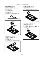
CP802
Move upward
Fig. 1-8-A
LCD PCB
Cable
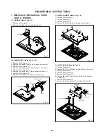
1-8: LCD PCB (Refer to Fig. 1-8-B)
1.
2.
3.
4.
5.
6.
7.
Disconnect the following connectors:
(CP102, CP103, CP104, CP802 and CP3805).
(Remove CP802 cable as shown Fig. 1-8-A.)
Remove the screw (1).
Remove the MPEG Shield.
Remove the 4 screws (2).
Remove the PCB Angle in the direction of arrow (A).
Remove the 4 screws (3).
Remove the LCD PCB in the direction of arrow (B).
1-10: POWER PCB (Refer to Fig. 1-10)
1.
2.
3.
Disconnect the following connector:
(CP3802).
Remove the 4 screws (1).
Remove the Power PCB in the direction of arrow.
Fig. 1-10
(1)
(1)
(1)
(1)
Power PCB
1-9: BACK LIGHT PCB (Refer to Fig. 1-9)
1.
2.
3.
Disconnect the following connectors:
(CP3803, CP7001, CP7002, CP7003, CP7004, CP7005
and CP7006).
Remove the 4 screws (1).
Remove the Back Light PCB in the direction of arrow.
Fig. 1-9
(1)
(1)
(1)
(1)
Back Light PCB
(2)
(2)
(2)
PCB Angle
MPEG Shield
(2)
Fig. 1-8-B
(1)
(A)
(B)
(3)
(3)
(3)
(3)
LCD PCB
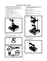
1-11: SIDE JACK PCB (Refer to Fig. 1-11)
1.
2.
3.
Disconnect the following connector:
(CP705).
Remove the 3 screws (1).
Remove the Jack Plate, Jack Shield and Side Jack PCB
in the direction of arrow.
Fig. 1-11
(1)
Side Jack PCB
(1)
(1)
Jack Plate
Jack Shield
Содержание CFTD2052
Страница 71: ...M5N1 06A O R NO SPEC NO W555001...

