


FS1-X v1.1
www.aja.com
37
Stand Alone Tests
The stand alone tests can be performed without a computer, using the FS1-X front panel
controls and rear connections.
The following procedures assume the FS1-X is at factory defaults (taken from a newly
opened box). If not set to defaults, the FS1-X may behave differently.
First Power Up
The following workflow powers up the FS1-X and demonstrates some example alarms.
Setup
• Ensure the FS1-X is completely disconnected (all video, audio, network, and power
connector ports are empty).
Procedure
1. Connect both FS1-X power cords to mains AC and allow time for the unit to boot up.
Observe the front panel LEDs.
• If the FRC PRES LED lights blue, your FS1-X is equipped with the FRC option and is
able to operate in either 1 Channel or 2 Channel Mode. If this LED is off, your unit
can only operate in 2 Channel mode.
• The ALARM LED will light red, indicating an alarm condition, and the REF LED will
be off. By default the F1-X is configured to operate genlocked to an external
reference signal.
2. Press the front panel
STATUS
button, then turn the
SELECT
knob to view various
Status menus.
• The Status menus will report No Input for the Video Processor video inputs (the
ports are disconnected), and the
GEN
(Genlock) parameter will report
Ref
(configured for external reference) but will also report
No Input
or
No Ref
.
3. Connect a 525i color black reference signal to one of the FS1-X Ref Loop BNCs.
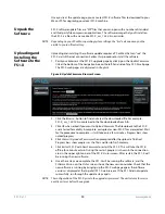
Activity
Indicators:
VID In 1/2
UFC, Proc Amp,
FRC Present,
FRC Active
FMT ERR 1/2
Power and
Status Indicators:
Pwr 1
Pwr 2
ID
Alarm
Alphanumeric Display:
Line 1=Parameter
Line 2=Parameter value
Line 3=Status/Legend
Line 4=Status/Legend
Select knob:
Scrolls and
selects menus;
Push to undo
changes.
Adjust knob:
Changes
selected value;
Hold down for
default value.
Menu Group Selection Buttons:
Press a button to select
a Menu Group in the display
3
4
Status Indicators:
Ref, Keyer, LAN, EXT
1
2
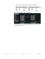
Vid 1 Format Status screen
Vid 1 Format Alarm Status screen
IN1
SDI 1
No Input
BKGD
Black
GEN
Ref
No Input
OUT1
525i59
IN1
SDI 1
OK
BKGD
Black
GEN
Ref
No Ref
OUT1
525i59


