


FS1-X v1.1
www.aja.com
22
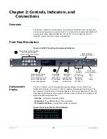
LED Indicators
Indicators on the front panel are multi-state LEDs that light when a condition is present.
They are conveniently arranged in groups to show specific subjects. For example,
indicators for the two video processors are aligned in two columns with 1 and 2 labeling
the tops of the columns.
The indicators and the conditions that cause them to light are as follows:
REMOTE
A multicolor LED that indicates the current control mode:
• Green = Local Only (front panel control only)
• Red = Remote Only (remote browser or panel control only)
• Amber = Local + Remote (front panel and remote control both enabled)
VID IN 1/2 (blue)
An active video input signal is detected for Channel 1 or 2.
UFC (blue
The Universal Format Converter has been changed from the default setting.
PROC AMP (blue)
The Proc Amp has been changed from the default setting (it’s no longer at unity).
FMT ERR 1/2 (blue)
The selected input and output formats are incompatible for Channel 1 or Channel 2.
FRC PRES (blue)
Frame Rate Converter option is present.
FRC ACTIVE (blue)
Frame Rate Converter is actively converting frame rates.
REF (blue)
The REF connector has an external reference video source applied.
KEYER (blue)
Reserved for future use.
LAN (blue)
The FS1-X is connected to an operational local area network. This indicator lights
momentarily when web browser selections are changed.
EXT (blue flashing)
Flashes when a remote control source (remote panel or GPI) has initiated a change in the
system.
PWR 1/2 (blue)
Power Supply 1 or 2 is operational and receiving power. Both PWR 1 and PWR 2 LEDs
must be lit to indicate redundant power is available.
ID (blue blinking)
Blinks on and off when you right-click on an FS1-X system name and choose Identify in
the web interface Network list. This action helps identify which FS1-X you’re controlling
when multiple FS1-X units are operated from a single computer. The ID LEDs on the front
and rear panels perform the exact same function. No matter which side of a rack you’re
facing, you’ll be able to see one of the LEDs.
Reset a value to the factory default value.
Set a number to the default value (typically zero).
Set a letter to a default value (typically space).
Hold down
ADJUST.
Take (commit) a change to an edited parameter.
Automatic after a few seconds for most parameters. For
multiple field parameters, push
ADJUST
momentarily to
save.
Abandon (undo) a change before committing.
Push
SELECT
momentarily.
Take (commit) a special action, such as a preset recall.
Push
ADJUST
momentarily.
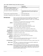
Table 1. SELECT and ADJUST Knob Operation Summary (continued)
Function
Knob Action


