background image


aj-aircraft.com


Page 20 


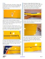
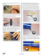
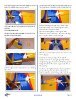
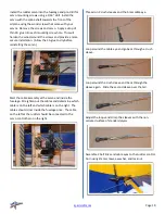
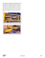
Center the rudder and position it aligned to the vertical 
stabilizer.  Tape the rudder to the vertical stabilizer to 
hold it centered.  Repeat the cable eye installation 
process on the rudder end of the cables with the servo 
powered up and centered.  

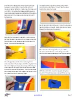
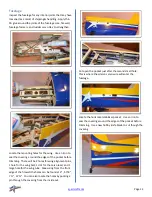
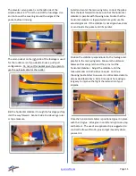
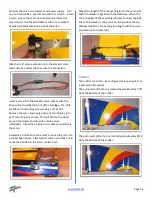
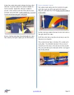
Pull the cable snug.  You don’t 

need to make the cable guitar string tight.

Remove the tape and adjust the cable lengths to center 
the rudder by turning the cable eyes into the ball links. 


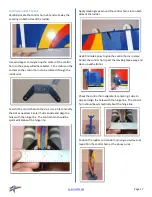
Push-Pull Rudder Control 

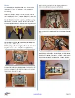
The rudder is built with control horn slots for the push-
pull control system and the pull-pull control system.  
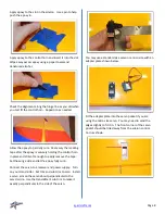
The push-pull control horn slot is located near the bottom 
of the rudder. 

Cut the covering to expose the lower control horn slot on 
the right side of the rudder.   

Instll the control horn using the same process as used on 
the alerons and elevator.  

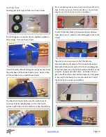
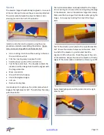
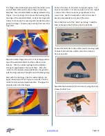
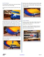
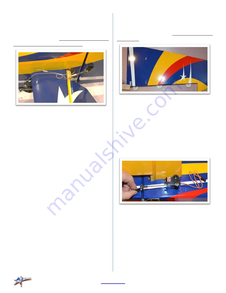
The pictures below shows a mockup of the rudder push- 
pull system.  The installation process of the servo and 
control horn is the same as the ailerons and the elevator.  
The pull-pull cables can be removed and the covering will 
need to be patched.


Содержание 10th Anniversary 51" Slick 540

Страница 1: ...10th Anniversary 51 AJ Slick 540 Assembly Instructions ...

Страница 2: ...ng All of AJ Aircraft s airframes have gone through many stages of extensive testing to ensure a high quality kit which results in a safe and reliable airframe when assembled properly Poor assembly practices along with substandard equipment will lead to an unsafe model The safe operation of this model is your responsibility and yours alone If you are a beginner or have never flown a model of this ...

Страница 3: ...ering 5 Wings 6 Landing Gear 10 Fuselage 12 Elevator 14 Rudder 16 Pull Pull Rudder Control 17 Push Pull Rudder Control 20 Motor 21 Cowl Canopy 22 Finishing Notes 22 Radio Installation Setup 24 Before starting read through the entire set of instructions to familiarize yourself with the process If there s ever a question contact AJ Aircraft 734 244 4015 ...

Страница 4: ...J Batteries o 4S 2800 mAH LiPo o 5s 2200 mAH LiPo o 6S 1800 mAH LiPo o Hook and loop battery strap ESC Castle Talon 60A Propeller Falcon 14x7 15x6 Electric ONLY 5 Channel Full Range Four high torque mini servos 13mm X 35mm X 29mm 2 or 50mm Spinner Servo extensions 2 x 6 for ailerons 1 x 18 for elevator 1 x 18 for rudder push pull only Servo Arms o 2 x 1 for ailerons o 1 x 1 for elevators o 1 x 2 5...

Страница 5: ... Your airplane is packaged in a double box to help protect it during shipping The best way top open the box is to cut the tape on the end folds of the first box and slide the second box out The lid on the second box simply lifts off ...

Страница 6: ...overing into the wood Using an iron sock will reduce scratches Genuine Ultracote covering White HANU870 True Red HANU866 Midnight Blue HANU885 Cub Yellow HANU884 At 200 220 F 93 104 C the adhesive on UltraCote becomes active allowing the covering to be attached to the model While 220 will fully bond the covering to the model it is well below the temperature that causes UltraCote to shrink At 300 F...

Страница 7: ... slots Be sure not to cut through to the top side covering The hinges should already be glued into the ailerons Give each of them a little pull to ensure they are securely attached It s better to find a loose hinge now rather than during a flight The wings are already slotted for the hinges Use a covering iron to secure the covering along the edge of the wings Look at the wing hinge slots closely ...

Страница 8: ...nd of the wing half Flex the aileron slightly and apply a few drops of thin CA glue to both sides of the hinge Again move the aileron back and forth to its maximum positions Once the end hinges are securely positioned you can apply a few drops of thin CA to both sides of the remaining hinges Use sand paper to roughen the lower portion of the control horns on both sides This will help the epoxy bon...

Страница 9: ...oft enough to easily remove the tape Set the wing aside and let the epoxy fully cure Connect the servo to a receiver and power supply Turn on your transmitter Set trim and sub trim to zero Install a servo arm on the servo about perpendicular to the servo s side Use the transmitter s sub trim to make it exactly perpendicular to the side of the servo You may use a standard size servo or a mico size ...

Страница 10: ...lon lock nut to connect a ball link to the servo control horn The brass ball in the link is offset The larger reveal side should be against the control horn and servo arm shown below Check the length of the assembly to the servo arm with the aileron level with the wing When the correct length of the assembly is found connect the ball link to the servo arm Always adjust the connecting rod length wi...

Страница 11: ...packing tape you may need to trim the width of the tape Roll the tape out with the sticky side up Lay a straight edge down on the tape and cut with a new blade To attach the filler block with hook and loop adhesive tape attach two pieces on the landing gear next to the screws Then cut or sand recesses into the filler block to accommodate the thickness of the hook and loop tape Start with shallow c...

Страница 12: ...lon lock nut and tighten Install the tailwheel using 2 of the 3 wood screws Position the joint of the tail wheel assembly directly over the rudder hinge line and mark the position of the screws Turn the screws into the fuselage and rudder Remove the screws add a drop of thin CA glue to each hole to strengthen the wood and reinstall the screws The third screw is used to secure the tiller arm to the...

Страница 13: ...l be 2 holes for wing alignment pins 1 hole for the wing bolt 1 slot for the servo lead and 1 large hole for the wing tube Measuring from the front edge of the firewall the holes can be found at 3 5 7 8 7 12 You can also locate the holes by pocking a pin through the covering from the inside out Cut open the pocket just after the second small hole This is where the aileron servo wire will enter the...

Страница 14: ... with the wing tube Notice that the horizontal stabilizer is tapered which may obscure the actual alignment If the stabilizer is not aligned use shims or sand inside the pocket until it s parallel Position the stabilizer perpendicular to the fuselage and parallel to the main wing tube Measure the distance between the canopy latch and the corners of the horizontal stabilizer Adjust the stabilizer u...

Страница 15: ... with 30 minute epoxy Check the alighment again Let cure Remove masing tape Use sandpaper to roughen up the jointer plate where it engages the right elevator half This will allow the epoxy will adhere better The horizontal stabilizer is already slotted for the hinges Use a covering iron to secure the covering along the edge of the stabilizer Look at the stabilizer hinge slots closely Make sure the...

Страница 16: ...an again Position the elevator as your did during the test fit Check it at the ends of the stabilizer Tape the elevator tightly in position algined to the stabilizer at each counter balance Tape across the hinge line to keep the elevator assembly straight After the epoxy has had plenty of time to cure remove all the masking tape Center the elevator by looking at the ends of the stabilizer Push the...

Страница 17: ...n the wood around the screws and provide a more secure installation Allow the CA glue to dry before reinstalling the servo Assemble a ball link to each end of a connecting rod Use a socket head screw a flat washer and a nylon lock nut to connect a ball link to the servo control horn Adjust the length of the connecting rod to the servo arm with the elevator aligned with the stabilizer When the corr...

Страница 18: ...eded Center it side to side and align the holes with the hinge line The control horn should be symmetrical about the hinge line Apply masking tape around the control horn slot on both sides of the rudder Use 30 minute epoxy to glue the control horns in place Center the control horn peal the masking tape away and clean up with alcohol Check the control horn alignment centering it side to side and a...

Страница 19: ...imum desired deflection Experiment with the hinge position finding the best fit before gluing Start with the top hinge Flex the rudder slightly and apply a few drops of thin CA glue to one side Flex the rudder to its maximum desired position Then glue the opposite side and other hinges Connect the servo to a receiver and power supply Turn on your transmitter Set trim and sub trim to zero Install a...

Страница 20: ...assembly at the servo end inside the fuselage Straighten out the cables and determine which cable is on the left and which cable is on the right The cables should cross inside the fuselage once The cable on the left at the rudder should be connected to the servo control horn on the right Thread on 2 crush sleeves and the brass cable eye Loop around the cable eye and go back through a crush sleeve ...

Страница 21: ...to the ball links Push Pull Rudder Control The rudder is built with control horn slots for the push pull control system and the pull pull control system The push pull control horn slot is located near the bottom of the rudder Cut the covering to expose the lower control horn slot on the right side of the rudder Instll the control horn using the same process as used on the alerons and elevator The ...

Страница 22: ...e the AJ3910 24p 660KV will require some additional work Start by temporarily mounting the X mount Use it as a template to drill 4 holes in the firewall 9 64 drill Remove the motor mount and enlarge the holes to 5 16 A little CA glue and a file will help clean up the carbon fiber strands and hole shape Test fit the X mount to the firewall and attach the motor using flat head screws from the back A...

Страница 23: ...ely tape it into position Drill a 1 16 hole through the cowl and the fuselage at the marks you made Remove the cowl and thread the screws into the fuselage holes Remove the screws and add a drop of CA clue to harden the wood around each hole When the glue is dry reinstall the cowl Finishing Notes Install your receiver using a piece of hook and loop tape on the receiver tray Then strap it in place ...

Страница 24: ...de the wing on making sure the alignment pins are engaged into the holes Fasten with the thumb screw Attach the aileron servo wire to a 6 extension and secure it with a safety clip Tie the wires back away from the rudder servo You don t want the wires to get snagged disconnecting or causing rudder issues ...

Страница 25: ...y hold the up line And a tail heavy CG will steepen the up line While the final setup is of personal preference these are some general guidelines to make your first flight a success Enjoy your new plane We at AJ Aircraft sincerely hope you enjoy flying the AJ Slick 540 Feel free to create a support ticket at aj aircraft com if you have any problems questions or suggestions Once you get a few fligh...

Отзывы: