-32-
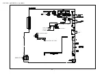
ELECTRICAL ADJUSTMENT-10/13 (HS MODEL)
TUNER ADJUSTMENT
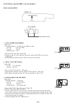
1. VT ADJUSTMENT (AM)
Requirement
• Measuring equipment : Digital multi-meter
Test point
: TP1(FFE801
4
pin),GND
Adjustment point : L773
(1) Adjust the reception frequency of the main unit to 1602KHz.
(2) Adjust L773 until the test point voltage (VT) is 8.5V±0.5V.
(3) Adjust the reception frequency of the main unit to 531KHz.
(4) Check that the test point (VT) voltage is about 1.3V.
2. VT CHECK (FM)
Requirement
• Measuring equipment : Digital multi-meter
Test point : TP1(FFE801
4
pin), GND
(1) Adjust the reception frequency of the main unit to 108.0MHz.
(2) Check that the test point (VT) voltage is about 8.0V.
(3) Adjust the reception frequency of the main unit to 87.5MHz.
(4) Check that the test point (VT) voltage is about 2.5V.
3. DC BALANCE ADJUSTMENT
Requirement
• Measuring equipment : Digital multi-meter
Test point
: TP4, 5
Adjustment point : L771
(1) Adjust the reception frequency of the main unit to 98.0MHz.
(2) Adjust L771 until the test point voltage difference between TP4 and TP5 is 0mV±20mV.
<ADJUSTMENT>
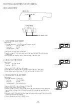
For AM adjustment, do wiring and connection as in the following.
4. IF ADJUSTMENT
Requirement
• Measuring equipment : Oscilloscope or Millivoltmeter
Test point
: TP7 (IC771 24pin), GND
Adjustment point : L772
(1) Adjust the setting of Standard Signal Generator (hereinafter S.S.G.) to 450KHz of 30% variation.
(2) While looking at the waveform on the oscilloscope, reduce the output level all the way.
(3) Adjust L802 until the waveform of the oscilloscope reaches the maximum.
60cm
SET
Standerd Signal Generaor
TP
Lch
Rch
GND
measuring equipment
Connect to the respective
V
DIGITAL MULTIMETER
TP1
GND
V
DIGITAL MULTIMETER
TP1
GND
V
DIGITAL MULTIMETER
VT
GND
GND
OSCILLOSCOPE
CH1
CH2
Lch
Rch
GND
Fig.2
Содержание XR-M161HS(S)
Страница 23: ... 22 FL ZCL 8 GRID ASSIGNMENT ANODE CONNECTION 1 1 GRID ASSIGNMENT ANODE CONNECTION ...
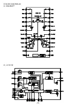
Страница 39: ... 38 IC M62495AFP AUTO RESET IC BLOCK DIAGRAM 2 2 IC LC72131D ...
Страница 51: ... 50 CD MECHANISM EXPLODED VIEW 1 2 DA 11T3C A M2 PIN 3 SW1 MOTOR C B 4 3 2 1 ...
Страница 53: ... 52 CD MECHANISM EXPLODED VIEW 2 2 KSM 213CDM 1 2 COVER 3 4 5 SPINDLE MOTOR M3 MOTOR C B A M2 ...
Страница 57: ...2 11 IKENOHATA 1 CHOME TAITO KU TOKYO 110 8710 JAPAN TEL 03 3827 3111 H251941 Printed in Singapore ...


