background image

28

27

All manuals and user guides at all-guides.com

Содержание LCX-157 HS

Страница 1: ... BASIC TAPE MECHANISM TN 21ZSC 2003 BASIC CD MECHANISM DA11T3C COMPACT DISC STEREO SYSTEM LCX 157 S M Code No 09 003 340 1N1 HS S MODEL CODE 86HR8 0117 B All manuals and user guides at all guides com a l l g u i d e s c o m ...

Страница 2: ...2 SPECIFICATIONS Design and specifications are subject to change without notice All manuals and user guides at all guides com ...

Страница 3: ... dangereuse exposition aux radiations ADVARSEL Usynlig laserståling ved åbning når sikkerhedsafbrydereer ude af funktion Undgå udsættelse for stråling This Compact Disc player is classified as a CLASS 1 LASER product The CLASS 1 LASER PRODUCT label is located on the rear exterior This set employs laser Therefore be sure to follow carefully the instructions below when servicing WARNING WHEN SERVICI...

Страница 4: ...IP F 0 01 C120 87 010 401 080 CAP ELECT 1 50V C121 87 010 396 080 CAP E 470 35 SME C122 87 010 213 080 C CAP S 0 015 50 B C123 87 010 196 080 CHIP CAPACITOR 0 1 25 C124 87 010 402 080 CAP ELECT 2 2 50V C126 87 010 408 080 CAP ELECT 47 50V C127 87 010 248 080 CAP ELECT 220 10V C128 87 010 393 080 CAP ELECT 100 35V C129 87 010 248 080 CAP ELECT 220 10V C130 87 010 393 080 CAP ELECT 100 35V C131 87 0...

Страница 5: ... 286 080 CAP U 0 01 25 C822 87 012 286 080 CAP U 0 01 25 C823 87 012 286 080 CAP U 0 01 25 C824 87 012 172 080 CAPACITOR CHIP U 10P CH C828 87 010 196 080 CHIP CAPACITOR 0 1 25 C828 87 010 196 080 CHIP CAPACITOR 0 1 25 C829 87 010 196 080 CHIP CAPACITOR 0 1 25 C859 87 012 286 080 CAP U 0 01 25 C861 87 012 199 080 CAP 220P C862 87 012 199 080 CAP 220P C864 87 010 405 080 CAP ELECT 10 50V C865 87 01...

Страница 6: ... 010 248 080 CAP ELECT 220 10V C549 87 010 198 080 CAP CHIP 0 022 C550 87 010 248 080 CAP ELECT 220 10V C551 87 010 178 080 CHIP CAP 1000P C552 87 010 197 080 CAP CHIP 0 01 DM C553 87 010 374 080 CAP ELECT 47 10V C555 87 010 403 080 CAP ELECT 3 3 50V C556 87 010 197 080 CAP CHIP 0 01 DM C559 87 010 315 080 C CAP S 27P 50 CH C560 87 010 263 080 CAP ELECT 100 10V C561 87 010 196 080 CHIP CAPACITOR 0...

Страница 7: ...0 5 0 35 104 L t W 2SA1296 2SC1815 KTC3198 2SC2714 2SD1306 DTC114TK DTC143TK DTC144EK RT1P141C PT1P144C 2SC4115 DTC124XS DTC343TS 2SA933 2SB1010 2SC2001 SS8050 2SD1381 B E C E C B E C B E C B E C B D S G 2SK543 Regarding connectors they are not stocked as they are not the initial order items The connectors are available after they are supplied from connector manufacturers upon the order is receive...

Страница 8: ...1 2 3 4 5 6 7 8 9 10 11 12 13 14 A B C D E F G H I J K 10 9 WIRING 1 MAIN All manuals and user guides at all guides com ...

Страница 9: ...12 11 IC BLOCK DIAGRAM IC M62495AFP IC LA1837NL IC LA6541D IC LC72131D IC BU1920FS All manuals and user guides at all guides com ...

Страница 10: ...AM J105 INV IC301 CASSETTE PER AMP BIAS OSC BEAT CUT REG REG REG REG REG SW C121 137 MODEL 330 25V 157 MODEL 470 35V HOLD DET HOLD DET POWER AMP IC102 FUNCTION SWITCH POWER CONT POWER ON OFF J101 JACK PIN 3P MSP J101 JACK 3 5 ST PHONES SPEAKERS F101 3 15A 250V 230V 50Hz 1 8k 1 8k All manuals and user guides at all guides com ...

Страница 11: ... AMP LW OSC SW AM IF ADJ DC BALANCE ADJ IC771 FM AM IF STEREO TUNER SYSTEM SIGNAL PB FM REC AM BAND SW D942 D944 L773 2 2µH TUNER ON OFF SWITCH 0 015 0 015 BEAT VM 5V ROCL RODA SIG FM 75Ω MW LW LOOP J801 ANTENNA 1SS133 D5 R822 10K All manuals and user guides at all guides com a l l g u i d e s c o m ...

Страница 12: ...1 2 3 4 5 6 7 8 9 10 11 12 13 14 A B C D E F G H I J K 18 17 WIRING 2 CD FRONT INSERTED PARTS All manuals and user guides at all guides com ...

Страница 13: ...1 2 3 4 5 6 7 8 9 10 11 12 13 14 A B C D E F G H I J K 20 19 WIRING 3 CD FRONT CHIP PARTS All manuals and user guides at all guides com ...

Страница 14: ...22 21 SCHEMATIC DIAGRAM 3 FRONT IRDDT IR200 All manuals and user guides at all guides com ...

Страница 15: ...24 23 SCHEMATIC DIAGRAM 4 CD All manuals and user guides at all guides com ...

Страница 16: ...26 25 VOLTAGE CHART All manuals and user guides at all guides com a l l g u i d e s c o m ...

Страница 17: ...28 27 All manuals and user guides at all guides com ...

Страница 18: ...30 29 ELECTRICAL ADJUSTMENT All manuals and user guides at all guides com ...

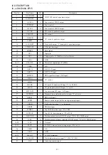
Страница 19: ...pen drain output Clock shift output L during shift open drain output 8 Hz time base input Reset input Input pin Output pin for 32 768kHz crystal oscillation GND Main clock input output 5 76 MHz 5V KEY0 A D input KEY1 A D input RDS signal level input A D input CD control CD door SW detection SW input L at CLOSE CD pick up detection SW input L at ON Tape detection SW input A D input Monaural stereo ...

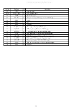
Страница 20: ...D common output Initial setting input Beat selector output H during selection CMOS output GND 5V Not used Tuner chip enable output CMOS output H output during CD function CMOS output H output during TU function Open drain output REC mute output H during mute Open drain output REC PB select output H during PB Open drain output Mute output H during mute Open drain output Power control output H at ON...

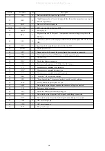
Страница 21: ...d VR pins Tracking phase compensation setting pin Tracking jump signal kick pulse amplitude setting pin Tracking control signal output pin Focusing control signal output pin Pin to which external focusing phase compensation constants are connected between the FD and FA pins Pin to which external focusing phase compensation constants are connected between the FD and FA pins Pin to which external fo...

Страница 22: ...GND Output pin to which external focus search smoothing capacitor is connected Tracking Balance Control EF balance variable range setting pin No connection Disc defect detector output pin Reference clock input pin 4 23 MHz of the DSP is input Microprocessor command clock input pin Microprocessor command data input pin Microprocessor command chip enable input pin Detect RF RF level detector output ...

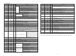
Страница 23: ... played back at H C2 flag output pin DIGITAL OUT output pin EIAJ format Test signal input pin with built in pull down resistor Be sure to connect to 0V Not used Set the pin to open L channel mute output pin L channel 1 bit DAC L channel power supply pin L channel output pin L channel GND Be sure to connect to 0V R channel GND Be sure to connect to 0V R channel 1 bit DAC R channel output pin R chan...

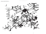
Страница 24: ... 10 11 12 13 14 15 16 17 18 19 20 21 22 23 23 24 25 26 27 28 29 7 HT SINK CHAS MAIN TN 21ZSC P C B P C B a a b b C C D D C H C D C C C C D F 31 D G G 34 33 F 32 35 36 30 B B E E A A A H H H H A A P C B 37 11 All manuals and user guides at all guides com ...

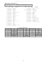
Страница 25: ...14 8A CLB 011 010 KEY P S 15 8Z CDB 170 010 BASE CHUCK 16 88 CD9 211 210 RING CHUCK 17 87 036 368 010 MAGNET 18 8A CLB 002 010 LID CD 19 8Z CL8 683 010 CONN ASSY 2P CD DOOR 20 8Z CL8 205 010 SPR T CD 21 8A CLB 003 010 CHAS CD 22 M8 ZZK E90 070 DA11T3C 23 88 CT6 206 010 CUSHION CD 24 8Z CL8 681 010 CONN ASSY 6P CD MOTOR 25 8A CLB 020 010 CABI REAR 26 8Z CL8 682 010 FF CABLE 16P 1 0 180MM 27 8Z CL8 ...

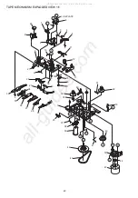
Страница 26: ...L F G E LUG PLATE 6 2 1 3 4 5 11 10 8 9 46 47 21 20 18 19 22 23 24 26 27 28 29 14 15 16 17 49 34 35 36 51 13 C C 30 7 25 37 38 48 B 50 45 44 K I D D 39 40 41 42 43 B H A 32 31 33 12 All manuals and user guides at all guides com a l l g u i d e s c o m ...

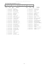
Страница 27: ...BUTTON LEVER 30 S1 821 100 700 FF GEAR 31 S1 921 050 060 SENSER 32 S1 921 053 100 TAKE UP REEL ASSY 33 S1 829 100 010 PACK SPRING 34 S1 921 050 150 S REEL HUB 35 S1 921 050 220 BACK TENSION SPRING 36 S1 921 140 220 REC BUTTON LEVER 37 S1 921 140 170 P S LEVER SPRING 38 S1 921 073 040 RF CLUTCH ASSY 39 S1 921 070 030 RF BELT 40 S1 921 260 020 CAM GEAR 41 S1 921 140 160 E ACTUATOR SPRING 42 S1 921 0...

Страница 28: ... 1 S2 121 A28 400 COVER GEAR 2 S2 511 A21 000 GEAR MIDDLE 3 S2 511 A21 100 GEAR DRIVE A S1 PN2 03R OSE SCR PAN PCS 2 3 B 87 261 073 410 SCR S TPG FLT 2 6 6 ALL M8 ZZK E90 070 DA11T3C B B A A SHAFT SLIDE 1 2 3 MOTOR C B SPINDLE MOTOR M3 CHASSIS SF P101NR All manuals and user guides at all guides com ...

Страница 29: ... 8A CLB 016 010 FRAME SPKR 4 86 CL9 214 010 HLDR CORD SPKR 5 8Z CL7 107 010 BADGE AIWA SILVER 6 8Z CL8 694 110 CORD SPKR GRY REF NO PART NO KANRI DESCRIPTION NO ACCESSORIES PACKAGE LIST 1 8A CLB 961 010 RC UNIT RC AAT11 2 87 A90 030 010 ANT LOOP AM NC C 3 87 A90 118 010 ANT WIRE FM Z All manuals and user guides at all guides com ...

Страница 30: ...2 11 IKENOHATA 1 CHOME TAITO KU TOKYO 110 8710 JAPAN TEL 03 3827 3111 737004 Printed in Singapore All manuals and user guides at all guides com ...

Отзывы: