


10
EN
FR
ES
IT
PT
DE
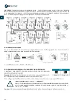
IMPORTANT:
The maximum number of zone modules connected without their own power supply to the Airzone VAF control
Board is: 6 zone modules connected to Blueface controllers or 10 zone modules connected to Think or Lite controllers. To add
more zone modules, it is necessary to install the supplementary power supply unit (Airzone VAF additional 12V power supply).
Every supplementary power supply unit is enough for 6 or 10 modules as stated before.
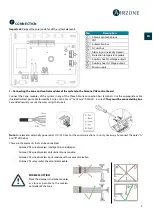
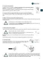
2.- Connecting the controllers
Connect each controller to the terminal corresponding to its zone module. Use the appropriate cable: shielded twisted pair
cable formed by 4 wires: 2x0.22 mm
2 +
2x0.5mm
2
(AWG 20 – 4 wired).
In case of Wireless controller, check it has the battery on.
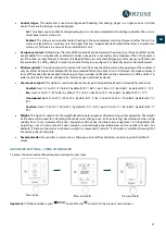
3.- Configuration and connection of the relay radiant heat control module
If you have a relay radiant heat control module, configure the SW2 microswitch
depending on the zones to control.
For example:
The relay to control the radiant element of a zone module with address 6 is the
R1 of the radiant heat control module with address configured for zones 6-10.
Once configured, perform the connection with the radiant elements to control per each relay output of the module.
Control relay specs: Imax = 1 A at 24/48 V, voltage-free.
Note that to control elements with a greater power, it is recommended to use contactors in accordance
with the power required. Remember to connect the neutral connector directly from the circuit to the
element to be controlled.
Important:
The Airzone system is not compatible with electric duct heaters, it may result in system malfunction and/or fire.
Terminals of zone module
Controller
SW2
Zones 1-5
Zones 6-10
Содержание VAF BLUEFACE
Страница 1: ...C l i p b o a r d P a g e N u m b e r Quick Installation Guide English Fran ais Espa ol...
Страница 2: ......