background image

12-4

TROUBLESHOOTING        

SM TQDCI 1-A.1 GB

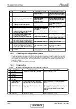
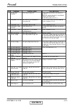
12.3.2 

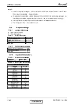
Fault Code for Indoor unit 

Pressing Mode button for long will activate diagnostic mode by the acknowledgment of 3 short 

beeps and lighting of COOL and HEAT LED’s. 

When Indoor diagnostics is displayed, all four LED’s (STBY, Operate, Filter, TMR) are on.   

Entering diagnostics in STBY mode allows only viewing of status (fault-display). 

In diagnostic mode, system problems / information will be indicated by blinking of Heat & Cool 

LED’s.

The coding method will be as follows:  

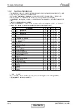
Heat led will blink 5 times in 5 seconds, and then will be shut off for the next 5 seconds. Cool 

Led will blink during the same 5 seconds according to the following table: 

No 

Fault 

Name 

5 4 3 2 1 

1 RT-1 

is 

disconnected 

2 RT-1 

is 

shorted 

3 RT-2 

is 

disconnected 

1 1 

4 RT-2 

is 

shorted 

1

… Reserved 

1

1

7 Communication 

mismatch 

1 1 1 

8 No 

Communication 

1

9 No 

Encoder 

1

1

10 

Reserved 

0 1 0 1 0 

11 

Outdoor 

Unit 

Fault 

0 1 0 1 1 

… Reserved 

17 Defrost 

protection 

1

18 Deicing 

Protection 

1

19 Outdoor 

Unit 

Protection 

1 1 

20 Indoor 

Coil 

HP 

Protection 

1

 21 

Overflow Protection 

1

1

1

… Reserved 

24 

EEPROM Not Updated 

1

1

25 Bad 

EEPROM 

1

1

1

26 Bad 

Communication 

1

1

1

27 Using 

EEPROM 

data 

1  1 

1 1 

28 Model 

1  1  1 

29 Model 

1  1  1 

1

30 

Model 


1 1 1 1 

31 

Model 

1 1 1 1 1 

1 - ON, 

0 - OFF 

Only one code is shown. Order of priority is lower to the higher number. Diagnostics is 

continuously ON as long power is on. 

CONTENTS

Содержание K 12 DCI

Страница 1: ...ro DCI Indoor Units Outdoor Units FLO 9 DCI TRIO 72 DCI QUTTRO 80 DCI FLO 12 DCI FLO 18 DCI SX 9 DCI SX 12 DCI SX 18 DCI BS 12 DCI K 9 DCI K 12 DCI K 18 DCI OCTOBER 2008 REFRIGERANT R410A HEAT PUMP SM TQDCI 1 A 1 GB CONTENTS ...

Страница 2: ...hanged pages are Original 0 June 2005 Total number of pages in this publication is 107 consisting of the following Page No Revision No Page No Revision No Page No Revision No Title 1 A 1 i 1 1 1 1 4 1 2 1 2 4 1 3 1 3 2 1 4 1 4 2 1 5 1 5 10 1 6 1 6 2 1 7 1 7 2 1 8 1 8 2 1 9 1 9 2 1 10 1 10 2 1 11 1 11 18 1 12 1 12 6 1 13 1 13 2 1 Appendix A 1 Zero in this column indicates an original page Due to co...

Страница 3: ...ITIONS 3 1 4 OUTLINE DIMENSIONS 4 1 5 PERFORMANCE DATA 5 1 6 PRESSURE CURVES 6 1 7 ELECTRICAL DATA 7 1 8 WIRING DIAGRAMS ELECTRICAL CONNECTIONS 8 1 9 REFRIGERATION DIAGRAMS 9 1 10 TUBING CONNECTIONS 10 1 11 CONTROL SYSTEM 11 1 12 TROUBLESHOOTING 12 1 13 EXPLODED VIEWS AND SPARE PARTS LISTS 13 1 14 APPENDIX A 14 1 ...

Страница 4: ...atures FLO series Lego concept Products line of wall mounted floor ceiling cassette ducted with capacity modeBS of 2 5 3 5 and 5 0 kW Networking connectivity Pre charged system Dry contact inputs o STBY o Night in cool mode only o Power Shedding o Forced Mode operation Dry contact output Alarm Ready for Base heater connection and logic Cooling operation at outdoor temperature down to 100 C Heating ...

Страница 5: ...I Quattro 80 DCI R410A R410A 1 6 Indoor Unit combinations Trio Quattro Unit A Unit B Unit D Code Sum Unit A Unit B Unit C Unit D Code Sum 9 9 9 3 9 9 9 9 4 9 9 12 3 5 9 9 9 12 4 5 9 9 18 4 9 9 12 12 5 9 12 12 4 9 9 9 18 5 12 12 12 4 5 9 9 12 18 5 5 12 12 18 4 5 9 12 12 12 5 5 12 12 18 5 9 12 12 18 6 12 12 12 12 6 Nominal Indoor Units Combination CONTENTS ...

Страница 6: ...Power 63 64 Dimensions W D H mm 950 835 340 Weight Kg 69 Package W D H mm 1 070X510X940 Unit stacking 3 TUBING Refrigerant Charge Kg R410A 3 200 Tube size O D Liquid mm 3x 6 35 Suction mm 2x 9 53 1x 12 7 Connection method between the indoor and outdoor units Indoor outdoor Flared Height difference between indoor units Max 15m Height difference between indoor outdoor Max 15m Tubing length Max 25m f...

Страница 7: ...3 64 Dimensions W D H mm 950 835 340 Weight Kg 70 Package W D H mm 1 070X510X940 Unit stacking 3 TUBING Refrigerant Charge Kg R410A 3 400 Tube size O D Liquid mm 4x 6 35 Suction mm 3x 9 53 1x 12 7 Connection method between the indoor and outdoor units Indoor outdoor Flared Height difference between indoor units Max 15m Height difference between indoor outdoor Max 15m Tubing length Max 25m for one ...

Страница 8: ...DCI Specifications Model Indoor Unit Type FLO 12 DCI Wall Mounted Installation Method FLARE Power Supply V Ph Hz 220 240 1 50 INDOOR Fan Type Quantity Crossflow 1 Airflow 2 Cooling Heating H M L m3 hr 550 580 450 480 350 370 Sound Power Level 3 Cooling Heating L H dB A 39 52 39 52 Sound Pressure Level 4 Cooling Heating L H dB A 26 39 26 40 Condensate Drain Tube I D mm 16 Dimensions W H D mm 810 285 2...

Страница 9: ...Type K 9 DCI Cassette Installation Method FLARE Power Supply V Ph Hz 220 240 1 50 INDOOR Fan Type Quantity Centifugal 1 Airflow 2 Cooling Heating H M L m3 hr 530 600 500 530 435 450 Sound Power Level 3 Cooling Heating L H dB A 42 48 42 47 Sound Pressure Level 4 Cooling Heating L H dB A 32 38 32 37 Condensate Drain Tube I D mm 16 Dimensions W H D mm 571 287 571 Weight kg 22 7 Package Dimensions W H ...

Страница 10: ...moval L hr 1 5 2 3 6 K 18 DCI Specifications Model Indoor Unit Type K 18 DCI Cassette Installation Method FLARE Power Supply V Ph Hz 220 240 1 50 INDOOR Fan Type Quantity Centifugal 1 Airflow 2 H M L m3 hr 730 630 510 Sound Power Level 3 L H dB A 46 59 Sound Pressure Level 4 L H dB A 36 48 5 Condensate Drain Tube I D mm 16 Dimensions W H D mm 571 287 571 Weight kg 28 Package Dimensions W H D mm 685 ...

Страница 11: ...tions Model Indoor Unit Type SX 12 DCI Floor ceiling Installation Method FLARE Power Supply V Ph Hz 220 240 1 50 INDOOR Fan Type Quantity Centifugal 2 Airflow 2 Cooling Heating H M L m3 hr 450 400 300 Sound Power Level 3 Cooling Heating L H dB A 51 56 Sound Pressure Level 4 Cooling Heating L H dB A 45 38 Condensate Drain Tube I D mm 16 Dimensions W H D mm 820 630 190 Weight kg 22 Package Dimensions...

Страница 12: ...ecifications Model Indoor Unit Type BS 12 DCI Ducted Installation Method FLARE Power Supply V Ph Hz 220 240 1 50 INDOOR Fan Type Quantity Centifugal 2 Airflow 2 Cooling Heating H M L m3 hr 590 50 400 Sound Power Level 3 Cooling Heating L H dB A 52 59 Sound Pressure Level 4 Cooling Heating L H dB A 35 42 Condensate Drain Tube I D mm 16 Dimensions W H D mm 860 245 680 Weight kg 30 Package Dimensions W...

Страница 13: ...1 Cooling Indoor 27o C DB 19o C WB Outdoor 35 o C DB Heating Indoor 20o C DB Outdoor 7o C DB 6o C WB 3 1 Operating Limits Indoor Outdoor Cooling Upper limit 32o C DB 23o C WB 46o C DB Lower limit 21o C DB 15o C WB 10o C DB Heating Upper limit 27o C DB 24o C DB 18o C WB Lower limit 10o C DB 15o C DB 16o C WB Voltage 1PH 198 264 V 3PH N A CONTENTS ...

Страница 14: ...4 1 OUTLINE DIMENSIONS SM TQDCI 1 A 1 GB 4 OUTLINE DIMENSIONS 4 1 Indoor Unit FLO 9 12 DCI 4 2 Indoor Unit FLO 18 DCI CONTENTS ...

Страница 15: ...4 2 OUTLINE DIMENSIONS SM TQDCI 1 A 1 GB 4 3 Indoor Unit K 9 12 18 DCI 4 4 Indoor Unit SX 9 12 18 DCI CONTENTS ...

Страница 16: ...4 3 OUTLINE DIMENSIONS SM TQDCI 1 A 1 GB 4 5 Indoor Unit BS 12 DCI 4 6 Outdoor Units TRIO 72 QUATTRO 80 DCI 378 48 527 865 950 340 AIR INTAKE AIR OUTLET CONTENTS ...

Страница 17: ...1 783 683 2 541 3 36 A 9 18 2 44 4 88 7 32 1 86 9 00 2 203 659 3 046 3 32 A 12 18 3 46 3 46 6 92 1 86 9 00 2 075 683 2 246 3 33 A 12 12 2 93 4 39 7 32 1 86 9 00 2 203 659 3 055 3 32 A 9 9 9 2 40 2 40 2 40 7 20 2 69 8 98 2 240 949 3 049 3 21 A 9 9 12 2 20 2 20 2 93 7 33 2 69 9 00 2 281 949 3 157 3 21 A 9 9 18 1 83 1 83 3 66 7 32 2 69 9 00 2 278 962 3 097 3 21 A 9 12 12 1 99 2 66 2 66 7 31 2 69 9 00...

Страница 18: ...3 12 2 38 2 38 18 3 90 3 90 9 9 1 66 1 66 3 32 9 12 1 67 2 33 4 00 9 18 1 59 3 81 5 40 12 12 2 35 2 35 4 70 12 18 1 99 3 43 5 42 9 9 9 1 56 1 56 1 56 4 69 9 9 12 1 43 1 43 1 99 4 86 9 9 18 1 19 1 19 2 86 5 24 9 12 12 1 30 1 81 1 81 4 92 9 12 18 1 10 1 53 2 63 5 26 12 12 12 1 66 1 66 1 66 4 98 12 12 18 1 42 1 42 2 44 5 28 Nominal Indoor Units Combination CONTENTS ...

Страница 19: ... 1 43 10 10 2 451 622 2 737 3 67 A 12 12 4 00 4 00 8 00 1 43 9 80 2 135 649 2 711 3 75 A 12 18 3 60 5 40 9 00 1 43 10 50 2 451 622 2 871 3 67 A 9 9 9 3 00 3 00 3 00 9 00 2 06 10 99 2 370 804 3 013 3 80 A 9 9 12 2 70 2 70 3 60 9 00 2 06 11 00 2 370 804 2 966 3 80 A 9 9 18 2 25 2 25 4 50 9 00 2 06 11 00 2 370 773 2 826 3 80 A 12 12 12 2 45 3 27 3 27 8 99 2 06 11 00 2 367 804 2 938 3 80 A 9 12 18 2 0...

Страница 20: ...15 2 899 3 22 A 9 9 18 2 00 2 00 4 01 8 01 2 90 9 00 2 466 928 2 851 3 25 A 9 12 12 2 17 2 90 2 90 7 97 2 90 9 00 2 445 915 2 851 3 26 A 9 12 18 1 87 2 50 3 74 8 11 2 90 9 00 2 476 928 2 821 3 28 A 12 12 12 2 69 2 69 2 69 8 07 2 90 9 00 2 372 955 2 841 3 40 A 12 12 18 2 31 2 31 3 47 8 10 2 90 9 00 2 372 928 2 802 3 42 A 9 9 9 9 2 00 2 00 2 00 2 00 8 00 3 70 9 17 2 490 1 091 2 937 3 21 A 9 9 9 12 1...

Страница 21: ...6 1 56 1 56 4 69 9 9 12 1 54 1 54 2 14 5 22 12 12 18 1 31 1 31 3 12 5 74 9 12 12 1 42 1 97 1 97 5 36 9 12 18 1 22 1 70 2 92 5 84 12 12 12 1 83 1 83 1 83 5 49 12 12 18 1 57 1 57 2 71 5 86 9 9 9 9 1 30 1 30 1 30 1 30 5 22 9 9 9 12 1 22 1 22 1 22 1 70 5 35 9 9 9 18 1 06 1 06 1 06 2 53 5 71 9 9 12 12 1 13 1 13 1 58 1 58 5 42 9 9 12 18 0 99 0 99 1 38 2 38 5 74 9 12 12 12 1 06 1 47 1 47 1 47 5 47 9 12 1...

Страница 22: ... 2 38 4 75 9 50 2 06 11 00 2 072 646 2 883 4 59 A 9 12 12 2 59 3 45 3 45 9 48 2 06 11 00 2 171 671 2 874 4 37 A 9 12 18 2 19 2 92 4 38 9 48 2 14 11 00 2 012 646 2 731 4 71 A 12 12 12 3 16 3 16 3 16 9 49 2 06 11 00 2 151 671 2 857 4 41 A 12 12 18 2 71 2 71 4 06 9 48 2 14 11 00 1 993 646 2 671 4 76 A 9 9 9 9 2 38 2 38 2 38 2 38 9 50 2 69 10 97 2 380 657 2 935 3 99 A 9 9 9 12 2 19 2 19 2 19 2 91 9 47...

Страница 23: ... 11 1 17 SC 0 98 1 00 1 03 1 05 1 07 PI 0 88 0 89 0 91 0 92 0 94 35 TC 0 87 0 94 1 00 1 06 1 13 SC 0 96 0 98 1 00 1 02 1 04 PI 0 97 0 99 1 00 1 02 1 03 40 TC 0 83 0 89 0 95 1 02 1 08 SC 0 93 0 95 0 97 1 00 1 02 PI 1 06 1 08 1 09 1 11 1 12 46 TC 0 77 0 83 0 90 0 96 1 02 SC 0 90 0 92 0 94 0 96 0 99 PI 1 17 1 19 1 20 1 22 1 23 LEGEND TC Total Cooling Capacity kW SC Sensible Capacity kW PI Power Input...

Страница 24: ...C 0 79 0 75 0 70 PI 0 86 0 92 0 98 2 1 TC 0 81 0 76 0 72 PI 0 89 0 95 1 01 7 6 TC 1 04 1 00 0 96 PI 0 94 1 00 1 06 10 9 TC 1 10 1 06 1 01 PI 1 00 1 06 1 12 15 12 TC 1 16 1 12 1 07 PI 1 05 1 11 1 17 15 24 TC 85 105 of nominal Protection Range PI 80 120 of nominal LEGEND TC Total Heating Capacity kW PI Power Input kW WB Wet Bulb Temp o C DB Dry Bulb Temp o C ID Indoor OU Outdoor 5 3 4 Capacity Corre...

Страница 25: ...2 0 98 1 05 1 11 1 17 SC 0 98 1 00 1 03 1 05 1 07 PI 0 88 0 89 0 91 0 92 0 94 35 TC 0 87 0 94 1 00 1 06 1 13 SC 0 96 0 98 1 00 1 02 1 04 PI 0 97 0 99 1 00 1 02 1 03 40 TC 0 83 0 89 0 95 1 02 1 08 SC 0 93 0 95 0 97 1 00 1 02 PI 1 06 1 08 1 09 1 11 1 12 46 TC 0 77 0 83 0 90 0 96 1 02 SC 0 90 0 92 0 94 0 96 0 99 PI 1 17 1 19 1 20 1 22 1 23 LEGEND TC Total Cooling Capacity kW PI Power Input kW WB Wet ...

Страница 26: ...TC 0 79 0 75 0 70 PI 0 86 0 92 0 98 2 1 TC 0 81 0 76 0 72 PI 0 89 0 95 1 01 7 6 TC 1 04 1 00 0 96 PI 0 94 1 00 1 06 10 9 TC 1 10 1 06 1 01 PI 1 00 1 06 1 12 15 12 TC 1 16 1 12 1 07 PI 1 05 1 11 1 17 15 24 TC 85 105 of nominal Protection Range PI 80 120 of nominal LEGEND TC Total Heating Capacity kW PI Power Input kW WB Wet Bulb Temp o C DB Dry Bulb Temp o C ID Indoor OU Outdoor 5 4 4 Capacity Corr...

Страница 27: ... 1 05 1 11 1 17 SC 1 01 1 03 1 04 1 06 1 07 PI 0 86 0 88 0 90 0 91 0 93 35 TC 0 88 0 94 1 00 1 06 1 12 SC 0 97 0 98 1 00 1 02 1 03 PI 0 97 0 98 1 00 1 02 1 03 40 TC 0 83 0 89 0 95 1 01 1 07 SC 0 93 0 94 0 96 0 97 0 99 PI 1 07 1 09 1 11 1 12 1 14 46 TC 0 77 0 83 0 89 0 95 1 00 SC 0 88 0 89 0 91 0 93 0 94 PI 1 20 1 21 1 23 1 25 1 27 LEGEND TC Total Cooling Capacity kW PI Power Input kW WB Wet Bulb T...

Страница 28: ...I 0 89 0 94 0 99 2 1 TC 0 80 0 74 0 67 PI 0 92 0 97 1 02 7 6 TC 1 07 1 00 0 93 PI 0 95 1 00 1 05 10 9 TC 1 12 1 06 0 99 PI 0 97 1 02 1 07 15 12 TC 1 18 1 11 1 04 PI 0 99 1 04 1 09 15 24 TC 85 105 of nominal Protection Range PI 80 120 of nominal LEGEND TC Total Cooling Capacity kW SC Sensible Capacity kW PI Power Input kW WB Wet Bulb Temp o C DB Dry Bulb Temp o C ID Indoor OD Outdoor 5 5 4 Capacity...

Страница 29: ... 0 98 1 05 1 11 1 17 SC 0 98 1 00 1 03 1 05 1 07 PI 0 88 0 89 0 91 0 92 0 94 35 TC 0 87 0 94 1 00 1 06 1 13 SC 0 96 0 98 1 00 1 02 1 04 PI 0 97 0 99 1 00 1 02 1 03 40 TC 0 83 0 89 0 95 1 02 1 08 SC 0 93 0 95 0 97 1 00 1 02 PI 1 06 1 08 1 09 1 11 1 12 46 TC 0 77 0 83 0 90 0 96 1 02 SC 0 90 0 92 0 94 0 96 0 99 PI 1 17 1 19 1 20 1 22 1 23 LEGEND TC Total Cooling Capacity kW PI Power Input kW WB Wet B...

Страница 30: ...TC 0 79 0 75 0 70 PI 0 86 0 92 0 98 2 1 TC 0 81 0 76 0 72 PI 0 89 0 95 1 01 7 6 TC 1 04 1 00 0 96 PI 0 94 1 00 1 06 10 9 TC 1 10 1 06 1 01 PI 1 00 1 06 1 12 15 12 TC 1 16 1 12 1 07 PI 1 05 1 11 1 17 15 24 TC 85 105 of nominal Protection Range PI 80 120 of nominal LEGEND TC Total Heating Capacity kW PI Power Input kW WB Wet Bulb Temp o C DB Dry Bulb Temp o C ID Indoor OU Outdoor 5 6 4 Capacity Corr...

Страница 31: ... 0 92 0 98 1 05 1 11 1 17 SC 0 98 1 00 1 03 1 05 1 07 PI 0 88 0 89 0 91 0 92 0 94 35 TC 0 87 0 94 1 00 1 06 1 13 SC 0 96 0 98 1 00 1 02 1 04 PI 0 97 0 99 1 00 1 02 1 03 40 TC 0 83 0 89 0 95 1 02 1 08 SC 0 93 0 95 0 97 1 00 1 02 PI 1 06 1 08 1 09 1 11 1 12 46 TC 0 77 0 83 0 90 0 96 1 02 SC 0 90 0 92 0 94 0 96 0 99 PI 1 17 1 19 1 20 1 22 1 23 LEGEND TC Total Cooling Capacity kW PI Power Input kW WB ...

Страница 32: ...TC 0 79 0 75 0 70 PI 0 86 0 92 0 98 2 1 TC 0 81 0 76 0 72 PI 0 89 0 95 1 01 7 6 TC 1 04 1 00 0 96 PI 0 94 1 00 1 06 10 9 TC 1 10 1 06 1 01 PI 1 00 1 06 1 12 15 12 TC 1 16 1 12 1 07 PI 1 05 1 11 1 17 15 24 TC 85 105 of nominal Protection Range PI 80 120 of nominal LEGEND TC Total Heating Capacity kW PI Power Input kW WB Wet Bulb Temp o C DB Dry Bulb Temp o C ID Indoor OU Outdoor 5 7 4 Capacity Corr...

Страница 33: ... 05 1 11 1 17 SC 1 01 1 03 1 04 1 06 1 07 PI 0 86 0 88 0 90 0 91 0 93 35 TC 0 88 0 94 1 00 1 06 1 12 SC 0 97 0 98 1 00 1 02 1 03 PI 0 97 0 98 1 00 1 02 1 03 40 TC 0 83 0 89 0 95 1 01 1 07 SC 0 93 0 94 0 96 0 97 0 99 PI 1 07 1 09 1 11 1 12 1 14 46 TC 0 77 0 83 0 89 0 95 1 00 SC 0 88 0 89 0 91 0 93 0 94 PI 1 20 1 21 1 23 1 25 1 27 LEGEND TC Total Cooling Capacity kW PI Power Input kW WB Wet Bulb Tem...

Страница 34: ... 0 70 0 63 PI 0 89 0 94 0 99 2 1 TC 0 80 0 74 0 67 PI 0 92 0 97 1 02 7 6 TC 1 07 1 00 0 93 PI 0 95 1 00 1 05 10 9 TC 1 12 1 06 0 99 PI 0 97 1 02 1 07 15 12 TC 1 18 1 11 1 04 PI 0 99 1 04 1 09 15 24 TC 85 105 of nominal Protection Range PI 80 120 of nominal LEGEND TC Total Heating Capacity kW PI Power Input kW WB Wet Bulb Temp o C DB Dry Bulb Temp o C ID Indoor OU Outdoor 5 8 4 Capacity Correction ...

Страница 35: ... 0 98 1 05 1 11 1 17 SC 0 98 1 00 1 03 1 05 1 07 PI 0 88 0 89 0 91 0 92 0 94 35 TC 0 87 0 94 1 00 1 06 1 13 SC 0 96 0 98 1 00 1 02 1 04 PI 0 97 0 99 1 00 1 02 1 03 40 TC 0 83 0 89 0 95 1 02 1 08 SC 0 93 0 95 0 97 1 00 1 02 PI 1 06 1 08 1 09 1 11 1 12 46 TC 0 77 0 83 0 90 0 96 1 02 SC 0 90 0 92 0 94 0 96 0 99 PI 1 17 1 19 1 20 1 22 1 23 LEGEND TC Total Cooling Capacity kW PI Power Input kW WB Wet B...

Страница 36: ...TC 0 79 0 75 0 70 PI 0 86 0 92 0 98 2 1 TC 0 81 0 76 0 72 PI 0 89 0 95 1 01 7 6 TC 1 04 1 00 0 96 PI 0 94 1 00 1 06 10 9 TC 1 10 1 06 1 01 PI 1 00 1 06 1 12 15 12 TC 1 16 1 12 1 07 PI 1 05 1 11 1 17 15 24 TC 85 105 of nominal Protection Range PI 80 120 of nominal LEGEND TC Total Heating Capacity kW PI Power Input kW WB Wet Bulb Temp o C DB Dry Bulb Temp o C ID Indoor OU Outdoor 5 9 4 Capacity Corr...

Страница 37: ... 0 92 0 98 1 05 1 11 1 17 SC 0 98 1 00 1 03 1 05 1 07 PI 0 88 0 89 0 91 0 92 0 94 35 TC 0 87 0 94 1 00 1 06 1 13 SC 0 96 0 98 1 00 1 02 1 04 PI 0 97 0 99 1 00 1 02 1 03 40 TC 0 83 0 89 0 95 1 02 1 08 SC 0 93 0 95 0 97 1 00 1 02 PI 1 06 1 08 1 09 1 11 1 12 46 TC 0 77 0 83 0 90 0 96 1 02 SC 0 90 0 92 0 94 0 96 0 99 PI 1 17 1 19 1 20 1 22 1 23 LEGEND TC Total Cooling Capacity kW PI Power Input kW WB ...

Страница 38: ... TC 0 79 0 75 0 70 PI 0 86 0 92 0 98 2 1 TC 0 81 0 76 0 72 PI 0 89 0 95 1 01 7 6 TC 1 04 1 00 0 96 PI 0 94 1 00 1 06 10 9 TC 1 10 1 06 1 01 PI 1 00 1 06 1 12 15 12 TC 1 16 1 12 1 07 PI 1 05 1 11 1 17 15 24 TC 85 105 of nominal Protection Range PI 80 120 of nominal LEGEND TC Total Heating Capacity kW PI Power Input kW WB Wet Bulb Temp o C DB Dry Bulb Temp o C ID Indoor OU Outdoor 5 10 4 Capacity Co...

Страница 39: ...9 1 05 1 11 1 17 SC 1 01 1 03 1 04 1 06 1 07 PI 0 86 0 88 0 90 0 91 0 93 35 TC 0 88 0 94 1 00 1 06 1 12 SC 0 97 0 98 1 00 1 02 1 03 PI 0 97 0 98 1 00 1 02 1 03 40 TC 0 83 0 89 0 95 1 01 1 07 SC 0 93 0 94 0 96 0 97 0 99 PI 1 07 1 09 1 11 1 12 1 14 46 TC 0 77 0 83 0 89 0 95 1 00 SC 0 88 0 89 0 91 0 93 0 94 PI 1 20 1 21 1 23 1 25 1 27 LEGEND TC Total Cooling Capacity kW PI Power Input kW WB Wet Bulb ...

Страница 40: ...76 0 70 0 63 PI 0 89 0 94 0 99 2 1 TC 0 80 0 74 0 67 PI 0 92 0 97 1 02 7 6 TC 1 07 1 00 0 93 PI 0 95 1 00 1 05 10 9 TC 1 12 1 06 0 99 PI 0 97 1 02 1 07 15 12 TC 1 18 1 11 1 04 PI 0 99 1 04 1 09 15 24 TC 85 105 of nominal Protection Range PI 80 120 of nominal LEGEND TC Total Heating Capacity kW PI Power Input kW WB Wet Bulb Temp o C DB Dry Bulb Temp o C ID Indoor OU Outdoor 5 11 4 Capacity Correcti...

Страница 41: ... 92 0 98 1 05 1 11 1 17 SC 0 98 1 00 1 03 1 05 1 07 PI 0 88 0 89 0 91 0 92 0 94 35 TC 0 87 0 94 1 00 1 06 1 13 SC 0 96 0 98 1 00 1 02 1 04 PI 0 97 0 99 1 00 1 02 1 03 40 TC 0 83 0 89 0 95 1 02 1 08 SC 0 93 0 95 0 97 1 00 1 02 PI 1 06 1 08 1 09 1 11 1 12 46 TC 0 77 0 83 0 90 0 96 1 02 SC 0 90 0 92 0 94 0 96 0 99 PI 1 17 1 19 1 20 1 22 1 23 LEGEND TC Total Cooling Capacity kW PI Power Input kW WB We...

Страница 42: ...TC 0 79 0 75 0 70 PI 0 86 0 92 0 98 2 1 TC 0 81 0 76 0 72 PI 0 89 0 95 1 01 7 6 TC 1 04 1 00 0 96 PI 0 94 1 00 1 06 10 9 TC 1 10 1 06 1 01 PI 1 00 1 06 1 12 15 12 TC 1 16 1 12 1 07 PI 1 05 1 11 1 17 15 24 TC 85 105 of nominal Protection Range PI 80 120 of nominal LEGEND TC Total Heating Capacity kW PI Power Input kW WB Wet Bulb Temp o C DB Dry Bulb Temp o C ID Indoor OU Outdoor 5 12 4 Capacity Cor...

Страница 43: ... 5 13 1 Cooling 5 13 2 Heating Tubing Length Capacity Ratio Cooling 1 Unit 0 76 0 81 0 86 0 91 0 96 1 01 1 06 0 5 10 15 20 25 30 Tubing Length m Capacity Ratio Tubing Length Capacity Ratio Heating 1 Unit 0 76 0 81 0 86 0 91 0 96 1 01 1 06 0 5 10 15 20 25 30 Tubing Length m Capacity Ratio CONTENTS ...

Страница 44: ...ion Factor FC Tubing L Factor FT Corrected Capacity KW CA D Room A FLO 9 1 43 1 00 0 92 0 95 CA 1 43x1 00x0 92x0 95 1 25 Room B FLO 12 1 91 1 00 0 92 0 985 CB 1 91x1 00x0 92x0 985 1 73 Room C K 12 1 91 1 03 0 92 1 00 CC 1 91x1 03x0 92x1 00 1 81 Room D FLO 18 2 87 1 00 0 93 0 93 CD 2 87x1 00x0 93x0 93 2 48 Total TC 1 25 1 73 1 81 2 48 7 27 Cooling Power Input calculation PA D KW Nominal x FM x FC x...

Страница 45: ...nician Mode WNG25 25 25 5m each 15 0 20 0 25 0 30 0 35 0 40 0 10 15 20 25 30 35 40 45 Outdoor DB Temperature ºC Bar g 32 23 29 21 27 19 24 17 22 15 Suction Pressure Cooling Technician Mode WNG25 25 25 5m each 6 00 7 00 8 00 9 00 10 00 11 00 12 00 10 15 20 25 30 35 40 45 Outdoor DB Temperature ºC Bar g 32 23 29 21 27 19 24 17 22 15 CONTENTS ...

Страница 46: ...m each 10 00 12 00 14 00 16 00 18 00 20 00 22 00 24 00 26 00 28 00 30 00 32 00 34 00 15 10 5 0 5 10 15 20 Outdoor DB Temperature ºC Bar g 25 20 15 Suction Pressure Heating Technician Mode WNG25 25 25 5m each 4 00 5 00 6 00 7 00 8 00 9 00 10 00 11 00 12 00 15 10 5 0 5 10 15 20 Outdoor DB Temperature ºC Bar g 25 20 15 CONTENTS ...

Страница 47: ...4 5 1 07 1 02 0 99 0 95 5 1 09 1 02 0 98 0 93 Tubing Length Pressure Ratio Cooling Cooling Ps Cooling Pd 0 98 0 99 1 00 1 01 1 02 0 10 20 30 40 50 Total Tubing Lengtht m Suction Pressure Ratio 0 98 0 99 1 00 1 01 1 02 Discharge Pressure Ratio Tubing Length Pressure Ratio Heating Heating Ps Heating Pd 0 94 0 95 0 96 0 97 0 98 0 99 1 00 1 01 1 02 0 10 20 30 40 50 Total Tubing Lengtht m Suction Press...

Страница 48: ...e WNG25 25 25 25 5m each 15 0 20 0 25 0 30 0 35 0 40 0 10 15 20 25 30 35 40 45 Outdoor DB Temperature ºC Bar g 32 23 29 21 27 19 24 17 22 15 Suction Pressure Cooling Technician Mode WNG25 25 25 25 5m each 6 0 7 0 8 0 9 0 10 0 11 0 12 0 13 0 10 15 20 25 30 35 40 45 Outdoor DB Temperature ºC Bar g 32 23 29 21 27 19 24 17 22 15 CONTENTS ...

Страница 49: ...5 25 5m each 10 00 12 00 14 00 16 00 18 00 20 00 22 00 24 00 26 00 28 00 30 00 15 10 5 0 5 10 15 20 Outdoor WB Temperature ºC Bar g 25 20 15 Suction Pressure Heating Technician Mode WNG25 25 25 25 5m each 4 00 5 00 6 00 7 00 8 00 9 00 10 00 11 00 12 00 15 10 5 0 5 10 15 20 Outdoor WB Temperature ºC Bar g 25 20 15 CONTENTS ...

Страница 50: ...0 20 30 40 50 60 70 Total Tubing Lengtht m Suction Pressure Ratio 0 98 0 99 1 00 1 01 1 02 Discharge Pressure Ratio Tubing Length Pressure Ratio Heating Heating Ps Heating Pd 0 94 0 95 0 96 0 97 0 98 0 99 1 00 1 01 1 02 0 10 20 30 40 50 60 70 Total Tubing Lengtht m Suction Pressure Ratio 0 94 0 95 0 96 0 97 0 98 0 99 1 00 1 01 1 02 Discharge Pressure Ratio CONTENTS ...

Страница 51: ...Quattro 80 DCI Indoor Combination FLO 9 FLO 12 K 12 FLO 18 Operation Mode Cooling Mode Conditions Indoor 22 CDB 15 WB Conditions Oudoor 30 CDB Tubing length 20m 10m 5m 25m 60m Cooling Pressure calculation Pressure Barg Nominal x FC x FT Unit Code Room A FLO 9 1 0 Room B FLO 12 1 5 Room C K 12 1 5 Room D FLO 18 2 0 ODU Code Total 6 0 Nominal Pressure Barg ODU Code Factor FC Tubing L Factor FT Corre...

Страница 52: ...nt 11 A Circuit breaker 20 A Power supply wiring No x cross section 3 X 2 5 mm2 Interconnecting cable No x cross section 4 X 1 5 X 1 5 mm2 For each IDU Note Inrush current is the current when power is up charging the DC capacitors at outdoor PCB Starting current is the current at comp start up NOTE Power wiring cord should comply with local lows and electrical regulations requirements CONTENTS ...

Страница 53: ...8 1 WIRING DIAGRAMS ELECTRICAL CONNECTIONS SM TQDCI 1 A 1 GB 8 WIRING DIAGRAMS ELECTRICAL CONNECTIONS 8 1 Outdoor Units TRIO 72 QUATTRO 80 DCI OMT CONTENTS ...

Страница 54: ...8 2 WIRING DIAGRAMS ELECTRICAL CONNECTIONS Service Manual Trio_Quttro DCI 8 2 Outdoor Units TRIO 72 QUATTRO 80 DCI ELECTRICAL CONNECTION CONTENTS ...

Страница 55: ...9 1 REFRIGERATION DIAGRAMS SM TQDCI 1 A 1 GB 9 REFRIGERATION DIAGRAMS 9 1 TRIO 72 DCI QUATTRO 80 DCI Outdoor Unit Refrigerant System Diagram OMT CONTENTS ...

Страница 56: ... 45 60 65 70 75 80 85 Valve Cap 13 20 13 20 18 25 18 25 40 50 Service Port Cap 11 13 11 13 11 13 11 13 11 13 1 Valve Protection Cap end 2 Refrigerant Valve Port use Allen wrench to open close 3 Valve Protection Cap 4 Refrigerant Valve 5 Service Port Cap 6 Flare Nut 7 Unit Back Side 8 Copper Tube CONTENTS ...

Страница 57: ...Sink Temperature sensor Hz Hertz 1 sec electrical frequency ICT Indoor Coil Temperature RT2 sensor IDU Indoor Unit MCU Micro Controller Unit OAT Outdoor Air Temperature sensor OCT ODU Coil Temperature sensor ODU Outdoor Unit OFAN Outdoor Fan PFC Power Factor Corrector RAC Residential A C RC Reverse Cycle Heat Pump RGT Return Gas Temperature sensor RPS Rounds per second mechanical speed RV Reverse ...

Страница 58: ...Q PRGH IRU FRROLQJ RU KHDWLQJ KHQ WKH VROHQRLG LV SRZHUHG V VWHP ZLOO ZRUN LQ KHDW PRGH 9 V SDQVLRQ YDOYH RSHUDWHG E VWHS PRWRU ZKLFK FRQWUROV WKH VL H RI WKH RUL FH 0 7KUHH 6HJPHQWV IRXU 3XVK EXWWRQV Input Filter PFC IPM Low voltage Power supply Application Control EEPROM IFAN COMP RV Base Heater EEV s Alarm Temperature Sensors Dry Contacts Communication Module Indoor Units Control Power Display ...

Страница 59: ...e input Used to force the operation mode of the system Alarm output indicates a failure at the system Alarm output will be activated when there in the following ODU Faults Protections 1 to 6 8 to 22 24 25 27 and 28 Alarm output will be OFF when the Fault Protection is cleared 11 2 8 Temperature Sensors CTT Compressor Top Temperature OAT Outdoor Air Temperature OMT Outdoor Middle Coil Temperature O...

Страница 60: ...tdoor and that indoor units with a large capacity are connected to the channels with EEV and refrigerant tubing that is suitable for large capacities Compare IDU s family and capacity code to the values stored at the EEPROM If more then one IDU is connected multi split application the following items should be checked o CodeA 1 5 o CodeB 1 5 o CodeC 1 5 o CodeD 2 o The sum of IDU codes ODUCodeLimi...

Страница 61: ...formed 1 The unit changes to SB 2 The system will scan all the communication 3 Each channel that is identified as no communication channel will be referred as STBY unit 4 The unit resumes its normal operation with only the operative channels 11 3 3 Temperature Measurements 11 3 3 1 Thermistor failures definition Thermistor Thermistor is Disconnected Thermistor is Shorted OCT Temp 40 C Temp 75 C OAT ...

Страница 62: ...n user setting unit will operate fan in selected speed In AutoFan user setting fan speed will be adjusted automatically according to the calculated NLOAD 11 4 3 Heat Mode NLOAD is calculated according to the difference between actual room temperature and user set point temperature by PI control In high medium low indoor fan user setting unit will operate fan in selected speed In AutoFan user setti...

Страница 63: ...tween 0 and MaxNLOADIF1C Hz When the room temperature is lower than the set point compressor will be switched OFF and indoor fan will cycle 3 minutes OFF 1 minute ON 11 4 6 Indoor Units Operation when Indoor Unit Mode is Different than Outdoor Unit Mode Open louvers according to user selection Indoor fan is forced to OFF 11 4 7 Heating Element Control Heating element can be lit on if LOAD 0 8 Maxi...

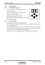
Страница 64: ...C commands OPERATION INDICATOR Lights up during operation Blinks for 300 msec to announce that a R C infrared signal has been received and stored Blinks continuously during protections according to the relevant spec section TIMER INDICATOR Lights up during Timer and Sleep operation FILTER INDICATOR Lights up when Air Filter needs to be cleaned COOLING INDICATOR Lights up when system is switched to...

Страница 65: ...using the Mode Switch on the unit FAN MODE INDICATOR Lights up in Fan Mode activated by local switches FAN SPEED INDICATORS L Lights up when IFAN setting is Low M Lights up when IFAN setting is Medium H Lights up when IFAN setting is High A Lights up when IFAN setting is Auto TEMP SETTING INDICATORS Each one of the seven indicators indicates the following SPT 18 20 22 24 26 28 30 o c The odd numbe...

Страница 66: ...t IDU which requests different mode than STBY mode will set the new operation mode The mode will change once all the units exit the current operation mode 2 Priority unit If an IDU is defined as a priority unit the operational mode will be defined according to that unit request unless the unit is at STBY mode In case priority unit is SB the mode will be set acceding to first request priority 3 For...

Страница 67: ...o the outdoor unit controller is based on the preliminary LOAD calculation the indoor fan speed and the power shedding function NLOAD limits as a function of indoor fan speed Indoor Fan Speed Maximum NLOAD Cooling Maximum NLOAD Heating Low Max NLOADIF1C 127 Medium Max NLOADIF2C 127 High Max NLOADIF3C 127 Turbo Max NLOADIF4C 127 Auto Max NLOADIF5C 127 NLOAD limits as a function of power shedding Mo...

Страница 68: ...ode Normal operation IDU inactive Compressor off SB 200 COOL 80 to 350 0 HEAT 70 to 400 60 to 140 200 11 5 3 2 Reaching target value rules For all cases except at EEV initialization procedure each EEV can move no more than 20 steps at a time When required the EEV s move one by one in sequence till the target position is achieved for every EEV The following diagram presents the EEV steps till the t...

Страница 69: ...it Basic EEV open loop Open Loop correction of active IDU units IDU Capacity Code Mode 1 2 3 4 1 5 2 COOL 220 200 170 150 10 25 HEAT 210 190 150 130 20 40 11 5 3 6 Balance time During the first 6 minutes after SB the correction is not calculated After that the correction value is updated every 30 seconds 11 5 3 7 EEV corrections The corrections in cool mode will keep the compressor in the proper o...

Страница 70: ...H RPM for cool and heat respectively In cool mode the OFAN will operate according to CTT or HST protection level Protection level Action SR D1 or D2 OFAN will add 100 RPM to the target speed Stop Compressor continue to operate for maximum 2 minutes at it last speed or until normal level is achieved 11 5 4 4 OFAN Force On condition If HST is higher than 70 C or defined as HST bad OFAN will remain ON...

Страница 71: ...he ODU receives the protection levels from each one of the IDU The protection levels are weighted according to the following table Protection Level Weight Normal 0 Stop Rise 1 D1 2 D2 3 Stop Compressor 0 The IDU protection level calculated weight according to the following average n weight prtoction IDU up round level protection IDU n i i 1 Where n The number of active IDU units 11 5 7 3 IDU Prote...

Страница 72: ...wer Shed dry contact input Power Shed input open Æ Power1 Power Shed input sort Æ Power2 The following table summarizes the basic levels of each protection Protection level Compressor Overheat cool CTT Compressor Overheat heat CTT Heat Sink HST Power1 Power2 Stop compressor 105 105 83 3600 2900 Down 2 100 100 81 3400 2750 Down 1 98 95 77 3200 2600 Stop rise 95 85 75 3100 2450 Normal 90 80 73 3050 ...

Страница 73: ...e If deicing time is shorter then former deicing time the deicing interval time will be increased If deicing time is longer then former deicing time the deicing interval time will be decreased 11 5 8 2 Deicing Protection Procedure COMP RV OFAN EEV ON HEAT COOL ON OFF EEVDeicerOpen Any T1 T2 T3 T3 T1 12 0 Threshold max 12 minutes DT OCT T1 T2 36 seconds T3 6 seconds 11 5 9 Condensate Water over Flo...

Страница 74: ...L ON Pump OFF 11 5 9 2 1 Level Logic used in all models except for floor ceiling models P2 P3 Level Don t care 1 Normal Don t care 0 Overflow ANY 0 ON NLOAD PUMP OFF ON OPER LED OFF Overflow Water Level Normal BLINK NLOAD is forced to 0 8 min 8 min Overflow when unit is ON Overflow when unit is OFF 8 min CONTENTS ...

Страница 75: ...an mode procedure All the connected indoor units will enter technician test at high indoor fan speed The outdoor unit will be working normally according to the run mode control logic except the following changes o The dry contacts inputs will be ignored o Protections will be operative for stop compressor not to be implemented in the current version o The compressor and the outdoor fan will be work...

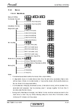
Страница 76: ...he right side of the third digit 11 8 2 Keys functionality o Scrolling will be done whenever the button is pressed o When scrolling alpha values if the scroll button is held in the selection will change at the rate of one step per second o When changing scrolling numeric value if the scroll button is held in the selection will change at the rate of one step per second After 2 seconds if the button...

Страница 77: ... ODU OdU Timer Tr Notes o The default presentation will be the mode of the unit Cl Ht Sb o In diagnostics menu xx means failure code Only the last active operative failure code will be shown if there is no active failure a sign will be shown the faults Numbers are the one shown in the single split table o The Parameters Changing and Status menus Technician menus will be enabled to be presented and...

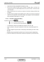
Страница 78: ...ly the parameters of the factory settings Acknowledge for restored parameters will be indicated by blinking RST for 3 seconds 11 8 3 2 Parameter Change Sub Menu Parameters changing Par Change Parameters CHG Restore Factory Parameters RST o The parameters names will be indicated by the sequence 001 002 999 o When a parameter is selected the parameter s stored value is presented aligned to the right...

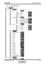
Страница 79: ... 0HQX 6WDWXV 6WW 8 7 7 7 7 7 2SHUDWLRQ 0RGH 2SHUDWLRQ 0RGH 2SHUDWLRQ 0RGH 2SHUDWLRQ 0RGH 2SHUDWLRQ 0RGH RDG RDG RDG RDG RDG 2 8 2SHUDWLRQ 0RGH 2 1 59 6SHHG 2 7 67 2 7 77 5 7 5 7 5 7 5 7 207 9 9 9 9 3RZHU 6 VWHP XUUHQW RPS 7LPHU RPSUHVVRU 7LPH CONTENTS ...

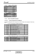
Страница 80: ...d in hours 11 9 Jumper settings 11 9 1 Jumper definitions 0 open disconnected 1 closed shorted 11 9 2 OFAN Jumpers OFAN use parameters J2 J1 Panasonic EHD80 0 0 Nidec SIC 71FW F170 1 0 1 Shinano 1 0 EEPROM 1 1 11 9 3 Compressor Jumpers Compressor use parameters J3 TNB220FLBM ROM 0 EEPROM 1 11 10 System Parameters 11 10 1 General parameters Parameter Default Value ODUCodeLimit 6 11 10 2 Protection ...

Страница 81: ...ICTVLSpeed ICT to go down to very low speed 28 ICTLSpeed ICT to start in very low speed 30 ICTHSpeed ICT to start in increase speed from very low 32 ICTTSpeed ICT to enable Turbo fan speed 40 ICTDef1 ICT to go back to normal 8 ICTDef2 ICT to stop rise when ICT decrease 6 ICTDef3 ICT to stop rise when ICT is stable 4 ICTDef4 ICT to Hz Down when ICT decrease 2 ICTDef5 ICT to Hz Down when ICT is stab...

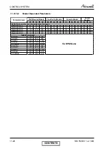
Страница 82: ... 40 40 40 N A N A MaxNLOADIF2C 53 53 62 53 53 60 53 56 60 N A N A MaxNLOADIF3C 120 120 120 120 120 90 120 90 90 N A N A MaxNLOADIF4C 127 127 127 127 127 90 127 90 90 N A N A MaxNLOADIF5C 127 127 127 127 127 90 127 90 90 N A N A Indoor Fan speeds IFVLOWC 700 700 700 IFLOWC 800 800 900 IFMEDC 900 950 1050 IFHIGHC 1050 1100 1200 IFTURBOC 1150 1200 1250 IFVLOWH 700 700 700 IFLOWH 800 850 900 IFMEDH 95...

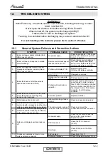
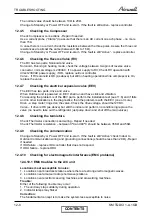
Страница 83: ... not warm Change to cool mode Outdoor unit is in opposite mode Change operation mode 4 Indoor fan does not start louvers are opened and Green LED is ON Problem with controller or capacitor Change to high speed and Check power supply to motor is higher than 130VAC for triack controlled motor or higher than 220VAC for fixed speed motors if OK replace capacitor if not OK replace controller 5 Indoor f...

Страница 84: ...eration 20 Indoor unit s Indicator s leds may flicker EMC interference to the A C unit Check for EMC problems 12 4 10 1 21 Other home appliances operation is faulty such as noise appears in the television picture or the picture is distorted or static occurs in the radio sound EMC interference by the A C unit Check for EMC problems 12 4 10 2 22 All others Specific problems of indoor or outdoor units ...

Страница 85: ...he problem presist replace controller If voltage is low recommend the customer to fix the power supply 18 No communication A No signals in line A 19 No communication B No signals in line B 20 No communication C No signals in line C 21 No communication D No signals in line D Check communication 12 4 9 22 Compressor Ilegal Speed Exceeds speed low limit See 13 23 System Configuration Changed Communic...

Страница 86: ...will blink during the same 5 seconds according to the following table No Fault Name 5 4 3 2 1 1 RT 1 is disconnected 2 RT 1 is shorted 3 RT 2 is disconnected 1 1 4 RT 2 is shorted 1 Reserved 1 1 7 Communication mismatch 1 1 1 8 No Communication 1 9 No Encoder 1 1 10 Reserved 0 1 0 1 0 11 Outdoor Unit Fault 0 1 0 1 1 Reserved 17 Defrost protection 1 1 18 Deicing Protection 1 1 19 Outdoor Unit Prote...

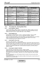
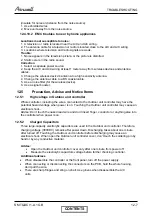
Страница 87: ...ok for broken or loosed cable lugs or wiring mistake s 12 4 2 Checking Main fuse Check 20A fuse on the Filter Board If burnt check the compressor fan or any other peripheral that can cause a short In case of a problematic peripheral replace it In case no problematic peripheral check the resistance on the DC bank B B on the Power board if it is less than 30 replace the controller Otherwise replace ...

Страница 88: ... the installation test see 11 6 and if fails and no other indications in the diagnostics than the problem is with the EEV one or more Drive a step motor ringed on the valve Check the drive voltage should be12VDC Valve if drive is OK as above but still the indoor unit perform no conditioning replace the valve no need to take out the refrigerant just pump down and shut off the main valves 12 4 8 Che...

Страница 89: ...r including the wires connected to the Outdoor unit controller may have the potential hazard voltage when power is on Touching the Outdoor unit controller may cause an electrical shock Advise Don t touch the naked lead wire and don t insert finger conductor or anything else into the controller when power is on 12 5 2 Charged Capacitors Three large capacity electrolytic capacitors are used in the O...

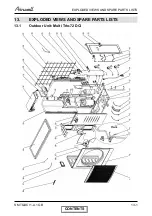
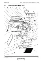
Страница 90: ...13 1 EXPLODED VIEWS AND SPARE PARTS LISTS SM TQDCI 1 A 1 GB 13 EXPLODED VIEWS AND SPARE PARTS LISTS 13 1 Outdoor Unit Multi Trio 72 DCI CONTENTS ...

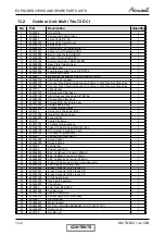
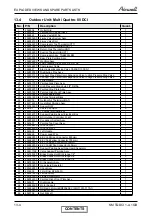
Страница 91: ...7300005 Display Board Assy 1 25 453031800 3 Poles Terminal Block 1 26 4526774 Outdoor Air Thermistor OAT 1 27 453175500 Guard Net Painting Assy 1 28 453083800 Support OAT 1 29 204107 Cable Clip Nylon 5 30 453031700 10 Poles Terminal Block 1 31 453256700 Support Painting Assy Electrical Box 1 32 452956100 DCI Outdoor Controller 3 1kW 1 33 452802500 Condensor System Assy 1 34 4523657 Painted Top Cov...

Страница 92: ...7300005 Display Board Assy 1 25 453031800 3 Poles Terminal Block 1 26 4526774 Outdoor Air Thermistor OAT 1 27 453175500 Guard Net Painting Assy 1 28 453083800 Support OAT 1 29 204107 Cable Clip Nylon 5 30 453031700 10 Poles Terminal Block 1 31 453256700 Support Painting Assy Electrical Box 1 32 452956100 DCI Outdoor Controller 3 1kW 1 33 452802500 Condensor System Assy 1 34 4523657 Painted Top Cov...

Страница 93: ...sy 1 25 453031800 3 Poles Terminal Block 1 26 4526774 Outdoor Air Thermistor OAT 1 27 453175500 Guard Net Painting Assy 1 28 453083800 Support OAT 1 29 204107 Cable Clip Nylon 5 30 453031700 10 Poles Terminal Block 1 31 453256700 Support Painting Assy Electrical Box 1 32 452956100 DCI Outdoor Controller 3 1kW 1 33 452802500 Condensor System Assy 1 34 4523657 Painted Top Cover Assy 1 35 453256800 G...

Страница 94: ...14 1 APPENDIX A SM TQDCI 1 A 1 GB APPENDIX A INSTALLATION AND OPERATION MANUAL INSTALLATION MANUAL TRIO 72 QUATTRO 80 DCI CONTENTS ...

Отзывы: