


Making the Electrical
Connections
Follow the steps below to connect the fan to your
household wiring. Use the wire connecting nuts
supplied with your fan. Secure the connectors with
electrical tape. Make sure there are no loose strands
or connections.
Step 1
Connect the fan supply (black) wire and light
supply (blue) wire to the black household supply wire
as shown in Figure 11.
Step 2
. Connect the neutral fan (white) wire to the
white neutral household wire.
REMEMBER
to disconnect the power. If you feel
that you do not have enough electrical wiring
knowledge or experience, have your fan installed by a
licensed electrician.
Step 3
Connect the two green fan ground wires,
located on the hanging ball and mounting plate, to the
household ground wire. When using Close-to-Ceiling
mounting, there is only one green ground lead from
the ceiling mounting plate since the ball/downrod
assembly is not used.
6.
Figure 9
Figure 10
Mounting
screws
(supplied with
electrical box)
Ceiling
mounting
plate
UL Listed
electrical
box
120V Wires
Washers
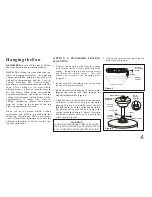
WARNING
WHEN USING THE STANDARD BALL/HANGER PIPE
MOUNTING, THE TAB IN THE RING AT THE BOTTOM OF
THE MOUNTING PLATE MUST REST IN THE GROOVE
OF THE HANGER BALL. FAILURE TO PROPERLY SEAT
THE TAB IN THE GROOVE COULD CAUSE DAMAGE TO
WIRING.
WARNING
THE HOOK AS SHOWN IN FIG. 10 IS ONLY
TO BALANCE FAN WHILE ATTACHING
WIRING. FAILURE TO HANG AS SHOWN
IN FIG. 10 MAY RESULT IN HOOK
BREAKING CAUSING THE FAN TO FALL.
HOOK MUST PASS FROM INSIDE TO
OUTSIDE OF CANOPY.
Close- to-Ceiling
Mounting
Standard Mounting
WARNING
TO REDUCE THE RISK OF FIRE OR
ELECTRIC SHOCK, DO NOT USE A WALL
MOUNTED SOLID STATE SPEED CONTROL
WITH THIS FAN. IT WILL PERMANENTLY
DAMAGE THE ELECTRONIC CIRCUITRY.
Step 4
After connecting the wires, spread
them apart so that the green and white wires
are on one side of the outlet box and the black
wire is on the other side.
Step 5
Turn the connecting nuts upward and
push the wiring into the outlet box.
Содержание P2501
Страница 1: ...P2501 Ceiling Fan Installation Manual...


