


if correct polarity is not observed when install-
ing the DC input cables.
CAUTION: Damage to the inverter will occur
if an external AC power source is applied to the
inverter’s AC outlet or its hardwire output.
CAUTION: Be sure both the inverter and the
external AC input circuit breaker or fuse (if
needed) are turned "OFF" during installation.
NOTE: All wiring must follow the National
Electric Code, Provincial, or other codes in
effect at the time of installation, regardless of
suggestions in this manual. All wires should
be copper conductors.
3.03 Mounting
3.03.1 Locate a suitable, secure flat
mounting surface as close to the battery as
possible without being in the same air tight
compartment.
3.03.2 The location should have ad-
equate ventilation and clearance to maintain
room temperature while the unit is operating.
At least 1/2 inch of clearance is required on all
sides.
3.03.3 Secure the unit with #8 or
larger screws or bolts in the mounting slots on
the flanges of the chassis.
3.04 Chassis Bonding Lug - FIG. 1
3.04.1 Connect a #8 gauge or greater
copper wire between the bonding lug on the
inverter and the earth grounding system or
the vehicle chassis.
3.05 Battery Wiring - FIG. 1
3.05.1
CAUTION: Make sure that hy-
drogen gas does not accumulate near the
battery by keeping the area well ventilated. A
spark may result when connecting the battery
wiring due to an initial charging of the internal
input capacitor.
3.05.2 Use stranded copper wire be-
tween the battery and inverter as indicated.
Aline fuse must be installed between the
battery and the inverter, within 18 inches of
the battery.
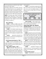
DC Input Wire Lengths (maximum)
and Fusing Guide
Distance(feet)
Model 1-19 20-40 Fuse
64/500 12 ga 10 ga 15
3.05.3 NOTE: Using smaller input
cable or longer length will greatly degrade
the inverter surge performance.
IMPORTANT NOTE FOR VEHICLE
INSTALLATION: Do not use the vehicle
chassis as the negative return in place of a
return cable. Use the same size cable as
the positive connection and run directly to
the battery.
3.05.4 Install the wires at the battery,
inverter and then fuse holder. Make sure that
clean, tight connections are made. Use care
not to touch the positive and negative wires
together. This will result in a violent spark and
could result in exploding batteries and fire.
3.05.5 The battery input terminals are
located in the inverter wiring compartment. A
spark may result when connecting the battery
wire, due to an initial charging of the internal
input capacitor.
3.05.6
CAUTION: Damage to the
inverter will occur if correct polarity is not
observed. This damage is
NOT covered by
warranty.
3.06 120 VAC Output
3.06.1
CAUTION: Do not connect an-
Page 3