background image

Page 15

 8 − After assembly, wipe excess cement from pipe at end

of fitting socket. A properly made joint will show a
bead around its entire perimeter. Any gaps may indi-
cate an improper assembly due to insufficient sol-
vent.

 9 − Handle joints carefully until completely set.

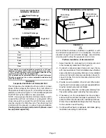
Venting Practices

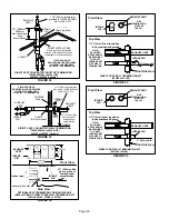
FIGURE 17

* See table 2 for allowable pipe.

Piping Suspension Guidelines

NOTE 

− Isolate piping at the point where it exits the outside wall or

roof in order to prevent transmission of vibration to the structure.

SCHEDULE 40

PVC − 5’

all other pipe*  − 3’

Wall

inside

outside

24" maximum
3/4" minimum

Wall Thickness Guidelines

insulation

(if required)

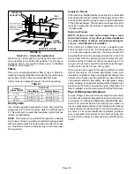
 1 − In areas where piping penetrates joists or interior

walls, hole must be large enough to allow clearance on
all sides of pipe through center of hole using a hanger.

 2 − When furnace is installed in a residence where unit is

shut down for an extended period of time, such as a
vacation home, make provisions for draining  conden-
sate collection trap and lines.

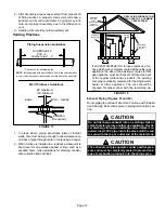
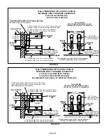
CHIMNEY

OR GAS

VENT

(Check sizing

for water

heater only)

FURNACE
(Replaced)

WATER

HEATER

OPENINGS

(To Adjacent

Room)

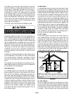
If an 92AF1UH/95AF1UH furnace replaces a fur-
nace which was commonly vented with another gas
appliance, the size of the existing vent pipe for that
gas appliance must be checked. Without the heat
of the original furnace flue products, the existing
vent pipe is probably oversized for the single water
heater or other appliance. The vent should be
checked for proper draw with the remaining ap-
pliance.

FIGURE 18

REPLACING FURNACE THAT

WAS PART OF A COMMON

VENT SYSTEM

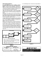
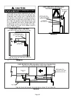
Exhaust Piping (Figures 21 and 22)

Route piping to outside of structure. Continue with installa-
tion following instructions given in piping termination sec-
tion.

CAUTION

Do not discharge exhaust into an existing stack or
stack that also serves another gas appliance. If verti-
cal discharge through an existing unused stack is re-
quired, insert PVC pipe inside the stack until the end
is even with the top or outlet end of the metal stack.

CAUTION

The exhaust vent pipe operates under positive pres-
sure and must be completely sealed to prevent leak-
age of combustion products into the living space.

Содержание 92AF1UH

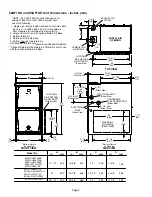
Страница 1: ...on service or maintenance can cause property damage person al injury or loss of life Installation and service must be performed by a licensed professional installer or equivalent service agency or the gas supplier Unit Dimensions 2 92AF1UH 95AF1UH Gas Furnace 3 Shipping and Packing List 3 Safety Information 3 Use of Furnace as a Construction Heater 4 General 5 Combustion Dilution Ventilation Air 5...

Страница 2: ...5 9 3 8 238 24 1 2 622 23 3 8 594 23 584 11 1 8 283 Model No 92AF1UH135P20D 95AF1UH045P08B 92AF1UH045P12B 92AF1UH070P08B 92 95UH1070P12B 95AF1UH09012B 92AF1UH090P12C 92 95AF1UH090P16C 92AF1UH110P16C 92 95AF1UH110P20C 6 9 16 167 Left 9 229 Right 23 584 19 3 4 19 1 Bottom Return Air Opening GAS PIPING INLET Either Side Side Return Air Opening Either Side 1Bottom Return Air Opening EXHAUST AIR OUTLET...

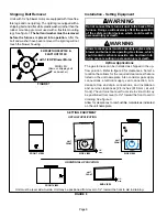
Страница 3: ...F HOUSE EXHAUST OUTLET COMBUSTION AIR INTAKE OUTSIDE OF HOUSE Safety Information WARNING Improper installation adjustment alteration service or maintenance can cause property damage personal injury or loss of life Installation and service must be performed by a licensed professional in staller or equivalent service agency or the gas sup plier CAUTION As with any mechanical equipment personal injur...

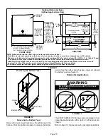
Страница 4: ...according to local codes In addition in the United States installation must conform with the current National Electric Code ANSI NFPA No 70 The National Electric Code ANSI NFPA No 70 is available from the following ad dress National Fire Protection Association 1 Battery March Park Quincy MA 02269 In Canada all electrical wiring and grounding for the unit must be installed according to the current ...

Страница 5: ...rovisions required to prevent freezing of condensate drain system CAUTION This furnace should not be installed in areas nor mally subject to freezing temperatures WARNING The State of California has determined that this prod uct may contain or produce a chemical or chemicals in very low doses which may cause serious illness or death It may also cause cancer birth defects or re productive harm WARN...

Страница 6: ... provide enough air by infiltration If the furnace is located in a building of tight construction with weather stripping and caulking around the windows and doors follow the procedures in the Air from Outside section Confined Space A confined space is an area with a volume less than 50 cubic feet 1 42 m3 per 1 000 Btu 29 kW per hour of the com bined input rating of all appliances installed in that...

Страница 7: ... minimum free area of 1 square inch 645 mm2 per 2 000 Btu 56 kW per total input rating of all equipment in the enclosure See figure 6 When ducts are used they shall be of the same cross sec tional area as the free area of the openings to which they connect The minimum dimension of rectangular air ducts shall be no less than 3 inches 75 mm In calculating free area the blocking effect of louvers gri...

Страница 8: ...r and burners are operating Gas fumes which could contain carbon monoxide can be drawn into living space resulting in personal injury or death Upflow Applications The gas furnace can be installed as shipped in the up flow position Refer to figure 9 for clearances Select a location that allows for the required clearances that are listed on the unit nameplate Also consider gas supply connections ele...

Страница 9: ...arances to accommodate condensate trap For installations on a combustible floor do not install the furnace directly on carpeting tile or other combustible materials other than wood flooring FIGURE 9 Return Air Guidelines Return air can be brought in through the bottom or either side of the furnace installed in an upflow application If the furnace is installed on a platform with bottom return make ...

Страница 10: ...VIEW 3 1 4 83 1 23 584 Overall Maximum 584 23 3 4 19 1 22 7 16 570 Overall Maximum SIDE RETURN AIR OPENINGS Either Side 5 5 8 143 1 Minimum 11 279 2 Maximum 14 356 683 26 7 8 7 1 4 184 FURNACE FRONT AIR FLOW IF BASE IS USED WITHOUT IAQ CABINET A SINGLE RETURN AIR PLENUM MUST COVER BOTH UNIT AND RETURN AIR BASE OPENINGS INDOOR AIR QUALITY CABINET PCO Filter Cabinet etc AIR BASE OPTIONAL RETURN 17 1...

Страница 11: ...ooling coils and supply and return air plenums must be supported separately FIGURE 15 TYPICAL HORIZONTAL APPLICATION Bracket typical Metal Strap typical Air Flow Internal Brace provided with kit NOTE When the furnace is installed on a platform or with the horizontal suspension kit in a crawlspace it must be elevated enough to avoid water damage accommodate drain trap and to allow the evaporator co...

Страница 12: ...st al ways be in place when the furnace is operating and it must not allow leaks Return Air Plenum NOTE Return air must not be drawn from a room where this furnace or any other gas fueled appliance i e water heater or carbon monoxide producing de vice i e wood fireplace is installed When return air is drawn from a room a negative pres sure is created in the room If a gas appliance is operating in ...

Страница 13: ...TTING SOLVENT CEMENT MARKING PVC CPVC Pipe and Fittings ULCS636 PVC CPVC Solvent Cement ABS to PVC or CPVC Transition Cement IMPORTANT 92AF1UH 95AF1UH exhaust and intake connections are made of PVC Use PVC primer and solvent ce ment when using PVC vent pipe When using ABS vent pipe use transitional solvent cement to make connections to the PVC fittings in the unit Use PVC primer and solvent cement...

Страница 14: ...cure the intake pipe to the connector if desired Use a drill or self tapping screw to make a pilot hole DANGER DANGER OF EXPLOSION Fumes from PVC glue may ignite during system check Allow fumes to dissipate for at least 5 minutes before placing unit into operation 1 Measure and cut vent pipe to desired length 2 Debur and chamfer end of pipe removing any ridges or rough edges If end is not chamfere...

Страница 15: ...nes CHIMNEY OR GAS VENT Check sizing for water heater only FURNACE Replaced WATER HEATER OPENINGS To Adjacent Room If an 92AF1UH 95AF1UH furnace replaces a fur nace which was commonly vented with another gas appliance the size of the existing vent pipe for that gas appliance must be checked Without the heat of the original furnace flue products the existing vent pipe is probably oversized for the ...

Страница 16: ...s of the pipe Therefore a 2 elbow must be added before the pipe is transitioned to any size larger than 2 This elbow must be added to the elbow count used to determine acceptable vent lengths Contact the Application Department for more information concerning sizing of vent systems which include multiple pipe sizes FIGURE 19 12 max of straight pipe Exhaust Pipe 12 Min NOTE Exhaust pipe MUST be glue...

Страница 17: ...98 98 94 5 56 41 19 90 75 43 18 112 112 93 93 89 6 51 36 14 85 70 38 13 107 107 88 88 84 7 46 31 n a 80 65 33 n a 102 102 83 83 79 8 41 26 75 60 28 97 97 78 78 74 9 36 21 70 55 23 92 92 73 73 69 10 31 16 65 50 18 87 87 68 68 64 Concentric Termination Elevation 0 4500 Number Of 90 Elbows Usedl 2 Pipe 2 1 2 Pipe 3 Pipe Model Model Model 045 070 090 110 135 045 070 090 110 135 045 070 090 110 135 1 6...

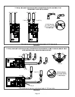
Страница 18: ...t length of 2 PVC pipe possible INTAKE 2 TRANSITION 3 2 EXHAUST INTAKE FIGURE 22 TRANSITION SIDE VIEW 2 2 2 2 or TYPICAL EXHAUST AND INTAKE PIPE CONNECTIONS IN HORIZONTAL DIRECT OR NON DIRECT VENT APPLICATIONS RIGHT HAND DISCHARGE SHOWN 3 2 45 MAX 45 MAX DO NOT transition from smaller to larger pipe in horizontal runs of exhaust pipe EXHAUST 12 max 2 When transitioning up in pipe size use the shor...

Страница 19: ...ntal Right Hand Air Discharge Application Shown INTAKE DEBRIS SCREEN Provided OR NOTE Debris screen may be positioned straight out preferred or with an elbow rotated to face down coupling PVC pipe Follow the next two steps when installing the unit in Non Direct Vent applications where combustion air is taken from indoors and flue gases are discharged outdoors 1 Use field provided materials and the...

Страница 20: ...E If winter design temperature is below 32 F 0 C exhaust piping should be insulated with 1 2 13mm Ar maflex or equivalent when run through unheated space Do not leave any surface area of exhaust pipe open to out side air exterior exhaust pipe should be insulated with 1 2 13mm Armaflex or equivalent In extreme cold cli mate areas 3 4 19mm Armaflex or equivalent may be necessary Insulation on outsid...

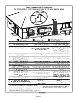
Страница 21: ... inlet Clearance above paved sidewalk or paved driveway located on public property Clearance under veranda porch deck or balcony 12 Equal to or greater than soffit depth 3 feet 9m 12 3 feet 9m within a height 15 feet 4 5m above the meter regulator assembly 3 feet 9m 6 inches 152mm for appliances 10 000 Btuh 3kw 12 inches 305mm for appliances 10 000 Btuh 3kw and 100 000 Btuh 30kw 36 inches 9m for a...

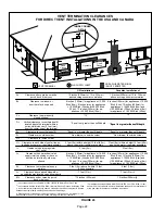
Страница 22: ...e paved sidewalk or paved driveway located on public property Clearance under veranda porch deck or balcony 12 7 feet 2 1m 3 feet 9m within a height 15 feet 4 5m above the meter regulator assembly 3 feet 9m 6 inches 152mm for appliances 10 000 Btuh 3kw 9 inches mm for appliances 10 000 Btuh 3kw and 50 000 Btuh 15 kw 12 inches 305mm for ap pliances 50 000 Btuh 15kw 6 inches 152mm for appliances 10 ...

Страница 23: ...e piping should termi nate straight down using two 90 elbows See figure 27 4 Exhaust piping must terminate straight out or up as shown A reducer may be required on the exhaust pip ing at the point where it exits the structure to improve the velocity of exhaust away from the intake piping See table 7 FIGURE 27 UNCONDITIONED ATTIC SPACE 1 2 13mm FOAM INSULATION IN UNCONDITIONED SPACE SIZE TERMINATIO...

Страница 24: ...pplications that include an exhaust termination tee The accelerator is not required 2 As required Flue gas may be acidic and may adversely affect some building materials If a side wall vent termination is used and flue gases will impinge on the building materials a corrosion resistant shield 24 inches square should be used to protect the wall surface If optional tee is used the protective shield i...

Страница 25: ...se the 1 1 2 accelerator sup plied with the kit NOTE Care must be taken to avoid recirculation of ex haust back into intake pipe 5 On field supplied terminations for side wall exit ex haust piping may extend a maximum of 12 inches 305mm for 2 PVC and 20 inches 508mm for 3 76mm PVC beyond the outside wall Intake piping should be as short as possible See figures 28 and 30 6 On field supplied termina...

Страница 26: ... provided in 71M80 44W92 kits for 045 070 EXHAUST VENT FIGURE 34 EXHAUST VENT INTAKE AIR 5 1 2 140mm Front View 12 305mm 5 127mm 18 MAX 457mm EXHAUST VENT INTAKE AIR OPTIONAL VENT TERMINATION FOR MULTIPLE UNIT INSTALLATION OF DIRECT VENT WALL TERMINATION KIT 22G44 44J40 30G28 or 81J20 Inches mm Side View 12 305mm Min above grade or average snow accumulation optional intake elbow FIGURE 35 1 2 13mm...

Страница 27: ...ipe is less than 12 in 305 mm above snow accumulation or other obstructions field fabricated piping must be installed FIGURE 38 ÉÉÉÉÉÉÉÉÉÉÉÉ 12 305 mm Minimum Above Grade or Average Snow Accumulation 1 2 13 mm FOAM INSULATION Field Furnished 5 127 mm 5 1 2 140 mm EXHAUST AIR INTAKE AIR GRADE 12 305 mm INTAKE AIR EXHAUST AIR GRADE WALL SUPPORT 12 305 mm Minimum Above Grade or Average Snow Accumulat...

Страница 28: ...ex haust piping may extend a maximum of 12 inches 305mm for 2 PVC and 20 inches 508mm for 3 76mm PVC beyond the outside wall See figure 41 FIGURE 40 NON DIRECT VENT ROOF TERMINATION KIT 15F75 or 44J41 UNCONDITIONED ATTIC SPACE 3 76mm OR 2 51mm PVC PROVIDE SUPPORT FOR EXHAUST LINES 12 305mm ABOVE AVE SNOW ACCUMULATION SIZE TERMINATION PIPE PER TABLE 7 1 2 13mm FOAM INSULATION FIGURE 41 1 2 13mm ARM...

Страница 29: ...from the cold end header box at the appropriate location on the side of the unit Install provided 3 4 NPT street elbow fitting into cold end header box Use Teflon tape or appropri ate pipe dope 3 Install the cap over the clean out opening at the base of the trap Secure with clamp See figure 51 FIGURE 44 CONDENSATE TRAP AND PLUG LOCATIONS Unit shown in upflow position NOTE In upflow applications wh...

Страница 30: ...it shown in upflow position with remote trap 5 max T o Drain PV CPipeOnly FieldProvidedVent Min 1 AboveCondensate DrainConnection 1 Min 2 Max CONDENSATE TRAP LOCATIONS Piping from furnace must slope down a minimum of 1 4 per ft toward trap FIGURE 46 92AF1UH 95AF1UH With Evaporator Coil Using A Separate Drain Condensate DrainConnection Field Provided Vent 1 min 2 max above condensate connection Eva...

Страница 31: ...tional Condensate Trap With Optional Overflow Switch FIGURE 49 92AF1UH 95AF1UH With Evaporator Coil Using a Common Drain 1 min to 2 Max above condensatedrain connection Condensate DrainConnection Evaporator drain line required FIGURE 50 92AF1UH 95AF1UH With Evaporator Coil Using a Common Drain Unit shown in horizontal left hand discharge position 4 min to 5 Max above condensatedrain connection 5 m...

Страница 32: ...Drain Connection In Unit Condensate Drain Connection In Unit Vent To Drain Condensate Drain Connection In Unit Optional Condensate Drain Connection OptionalDrainPipingFromTrap DrainTrapAssembly Furnished DrainTrap Assembly with 1 2 inch Piping DrainTrap Assembly with 3 4 inch Piping 1 2 inch 3 4 inch 1 25 mm Min 2 50 mm Max Above Top Of Condensate Drain Connection In Unit 1 25 mm Min 2 50 mm Max A...

Страница 33: ... 3 05m using suitable hangers or straps Install a drip leg in vertical pipe runs to serve as a trap for sediment or condensate 5 A 1 8 N P T plugged tap or pressure post is located on the gas valve to facilitate test gauge connection See figure 59 6 In some localities codes may require installation of a manual main shut off valve and union furnished by in staller external to the unit Union must be...

Страница 34: ...Gas Valve Gas Valve Bellows Grommet FIGURE 54 Horizontal Applications Possible Gas Piping Configurations GROUND JOINT UNION DRIP LEG MANUAL MAIN SHUT OFF VALVE GROUND JOINT UNION DRIP LEG MANUAL MAIN SHUT OFF VALVE GROUND JOINT UNION DRIP LEG MANUAL MAIN SHUT OFF VALVE Horizontal Application Left Side Air Discharge Horizontal Application Right Side Air Discharge NOTE BLACK IRON PIPE ONLY TO BE ROU...

Страница 35: ... WARNING CARBON MONOXIDE POISONING HAZARD Failure to follow the steps outlined below for each appliance connected to the venting system being placed into operation could result in carbon mon oxide poisoning or death The following steps shall be followed for each ap pliance connected to the venting system being placed into operation while all other appliances connected to the venting system are not...

Страница 36: ...configuration This terminal is energized when the indoor blower is operating Any accessory rated up to one amp can be connected to this terminal with the neutral leg of the circuit being connected to one of the provided neutral terminals If an accessory rated at greater than one amp is connected to this terminal it is necessary to use an exter nal relay One line voltage HUM 1 4 spade terminal is p...

Страница 37: ...Page 37 TYPICAL 92AF1UH 95AF1UH WIRING DIAGRAM FIGURE 57 ...

Страница 38: ...e injury or product or property damage Should the gas supply fail to shut off or if overheating occurs shut off the gas valve to the furnace before shutting off the electrical supply CAUTION Before attempting to perform any service or mainte nance turn the electrical power to unit OFF at dis connect switch BEFORE LIGHTING the unit smell all around the fur nace area for gas Be sure to smell next to...

Страница 39: ...ectrical power to to the unit 11 Set the thermostat to desired setting NOTE When unit is initially started steps 1 through 11 may need to be repeated to purge air from gas line 12 If the appliance will not operate follow the instructions Turning Off Gas to Unit and call your service techni cian or gas supplier Turning Off Gas to Unit 1 Set the thermostat to the lowest setting 2 Turn off all electr...

Страница 40: ...es sure 2 Start unit and allow 5 minutes for unit to reach steady state 3 While waiting for the unit to stabilize observe the flame Flame should be stable and should not lift from burner Natural gas should burn blue 4 After allowing unit to stabilize for 5 minutes record manifold pressure and compare to value given in table 10 NOTE Shut unit off and remove manometer as soon as an accurate reading ...

Страница 41: ... maining appliance The test should be conducted while all appliances both in operation and those not in operation are connected to the venting system being tested If the venting system has been installed improperly or if provisions have not been made for sufficient amounts of combustion air corrections must be made as outlined in the previous section 1 Seal any unused openings in the venting syste...

Страница 42: ...t is attached to the unit Electrical 1 Check all wiring for loose connections 2 Check for the correct voltage at the furnace furnace operating Correct voltage is 120VAC 10 3 Check amp draw on the blower motor with blower ac cess panel in place Motor Nameplate__________Actual__________ HEAT FAN OFF TIME IN SECONDS To adjust fan off timing reposition jumper across pins to achieve desired setting NO ...

Страница 43: ...ltage at the furnace furnace operating 3 Check amp draw on the blower motor Motor Nameplate__________Actual__________ Winterizing and Condensate Trap Care 1 Turn off power to the furnace 2 Have a shallow pan ready to empty condensate water 3 Remove the clean out cap from the condensate trap and empty water Inspect the trap then reinstall the clean out cap Cleaning the Burner Assembly If cleaning t...

Страница 44: ...recall Press and release the button to recall stored codes To clear codes press and hold the button for longer than 5 seconds Repair Parts List The following repair parts are available through your local dealer When ordering include the complete furnace mod el number listed on the CSA nameplate Example 92AF1UH045P08B All service must be performed by a licensed professional installer or equivalent ...

Страница 45: ...lled Properly Pipes Supported Condensate Trap Primed Line Sloped Heat Cable Installed and Operable if applicable 2 2 2 1 Horizontal Pipes Sloped if applicable UNIT SET UP Typical 3 4 Flter RETURN AIR Furnace Model Number_______________ Serial Number_________________ 3 DUCT SYSTEM SUPPLY AIR DUCT Sealed Insulated if necessary RETURN DUCT Sealed Filter Installed and Clean Grilles Unobstructed 4 VOLT...

Страница 46: ... 5 Supply External Static _______ Return External Static ______ Total External Static _______ CONDENSATE LINE 6 Leak Free VENT PIPE 7 Leak Free COOLING MODE INDOOR BLOWER AMPS______ 3 TEMPERATURE DROP Return Duct Temperature _________ Supply Duct Temperature _ _______ Temperature Drop _________ 4 DRAIN LINE 8 Leak Free THERMOSTAT Adjusted and Programmed Explained Operation to Owner 9 SUPPLY AIR Bl...

Страница 47: ... eight 8 feet above grade di rectly in line with the exhaust vent terminal for the hori zontally vented gas fueled heating appliance or equipment The sign shall read in print size no less than one half 1 2 inch in size GAS VENT DIRECT LY BELOW KEEP CLEAR OF ALL OBSTRUC TIONS 4 INSPECTION The state or local gas inspector of the side wall horizontally vented gas fueled equipment shall not approve th...

Отзывы: