background image

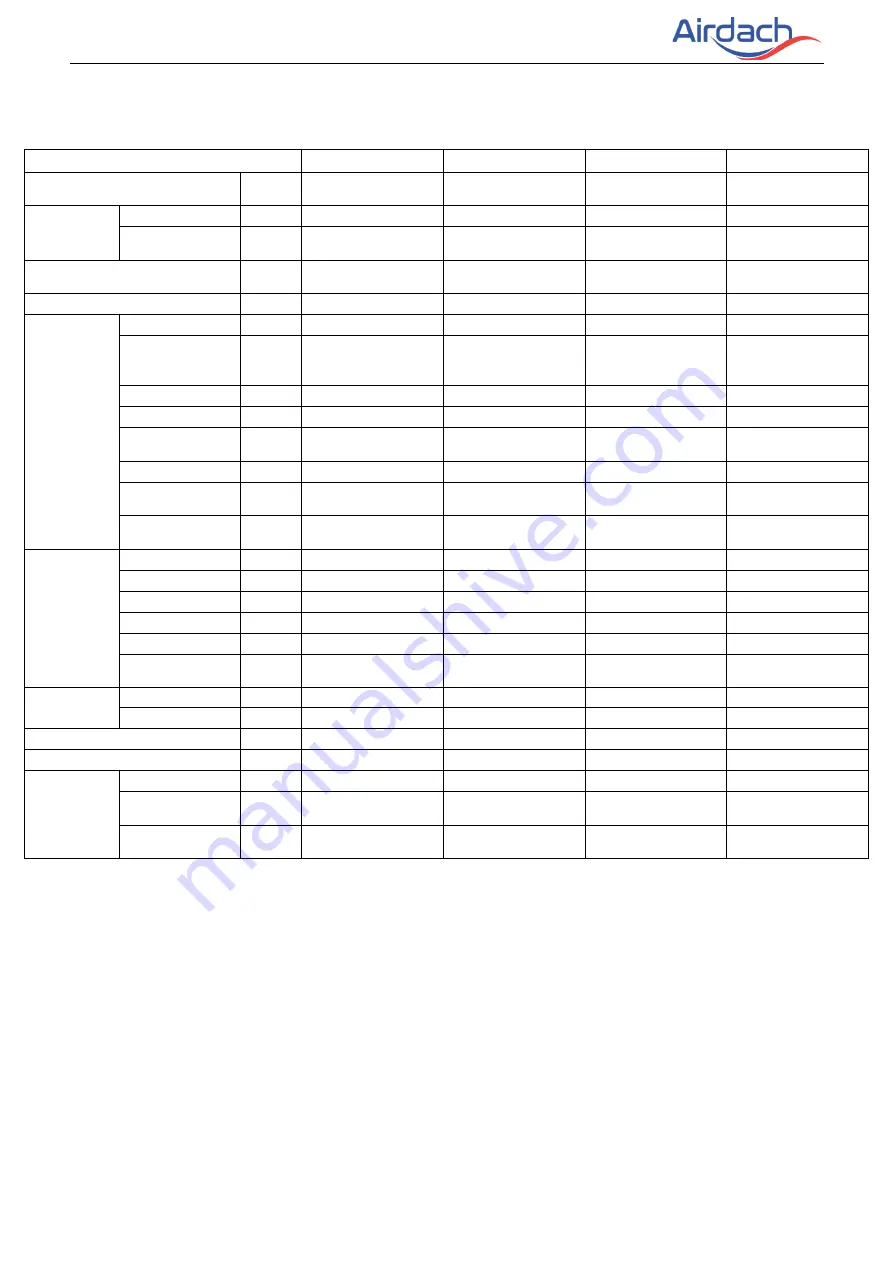
14SEER  AIR  COOLING ONLY  SYSTEM  TECHNICAL  MANUAL                                                       


Model 

AIDC3600NG1-D 

AIDC4200NG1-D 

AIDC4800NG1-D 

AIDC6000NG1-D 

Power supply 

V/Ph/

Hz 

208~230V/1N/60Hz  208~230V/1N/60Hz  208~230V/1N/60Hz  208~230V/1N/60Hz 

Cooling 

Capacity                Btu/h 

34500 

42000 

48000 

56500 

SEER 

Btu/h.

14.00   

14.00   

14.00   

14.00   

Indoor external static 
pressure 

Pa 

37 

37 

50 

50 

Throttle type 


TXV 

TXV 

TXV 

TXV 

Indoor coil 

Number of row 


4(row)×2(piece) 

4(row)×2(piece) 

5(row)×2(piece) 

5(row)×2(piece) 

Tube 
pitch(a)xrow 
pitch(b) 

in 

0.83×0.53 

0.83×0.53 

0.83×0.53 

0.83×0.53 

Fin spacing                                 

in 

1/16 

1/16 

1/16 

1/16 

Fin material 


Hydrophilic 

Hydrophilic 

Hydrophilic 

Hydrophilic 

Tube outside 
diameter 

in 

Ф ¼ 

Ф ¼ 

Ф ¼ 

Ф ¼ 

Tube material 


inner grooved 

inner grooved 

inner grooved 

inner grooved 

Coil length x 
height x width     

in 

17 7/16×16 

17/32×2 7/64 

17 7/16×16 

17/32×2 7/64 

19 27/32×21 1/2×2 

5/8 

19 27/32×21 1/2×2 

5/8 

Number of 
circuit 


12 

12 

Indoor fan 
motor 

Brand 


Kangbao 

Kangbao 

Kangbao 

Kangbao 

Type 


PSC


PSC


PSC


PSC


Input                        Amp 

1.81 

2.10 

2.63 

2.63 

Output 

Amp 

1.23 

1.36 

1.36 

Capacitor               

μF 

10 

10 

12 

12 

Speed 
(Lo/Me/Hi)   

rpm 

690/730/805 

610/723/839 

820/870/920 

820/870/920 

blower 

diameter 

in 

12-5/16 

12-5/16 

12-5/16 

12-5/16 

width 

in 

12-29/32 

12-29/32 

12-29/32 

12-29/32 

Indoor air flow         

CFM 

1161/1235/1376 

1208/1385/1562 

1434/1574/1695 

1434/1574/1695 

Indoor noise level   

dB(A) 

51 

54 

55 

55 

 
Indoor unit 

Unit (HxWxD) 

in 

45-3/4×19-2/3×22 

45-3/4×19-2/3×22 

53-1/8×22×24-1/2 

53-1/8×22×24-1/2 

Packing 
(HxWxD) 

in 

47.63×22.83×25.59 

47.63×22.83×25.59 

54.72×25.20×27.95 

54.72×25.20×27.95 


Net/Gross 
weight 

lbs 

134/146 

137/148 

176/190 

176/190 

 
Notes:     

1. Nominal cooling capacities are based on the following conditions:


Indoor temp: 80°FDB, 66°FWB; Outdoor temp: 95°FDB; Equivalent ref. piping: 5m (horizontal) 
2. Nominal heating capacities are based on the following conditions: 
Indoor temp: 68°FDB; Outdoor temp: 44°FDB, 43°FWB; Equivalent ref. piping: 5m (horizontal) 
3. Actual noise level may differ, depending on the room structure, etc., since these noise values are from an 
anechoic room. 

Содержание ACTC1814NG1-D

Страница 1: ...R410A 60Hz Universal Cooling Only System Technical Manual 14 SEER TOP DISCHARGE COOLING ONLY TECHNICAL MANUAL January 2021 Version A TM 14CO 01...

Страница 2: ...6 Part 3 Outdoor Unit 17 1 Specification 18 2 Dimension 19 3 Service Space 20 4 Wiring Diagrams 22 5 Electric Characteristics 22 6 Operation Limits 23 7 Sound Levels 24 8 Refrigerate diagram 25 Part 4...

Страница 3: ...14SEER AIR COOLING ONLY SYSTEM TECHNICAL MANUAL 1 Part 1 General Information 1 Model Names of Indoor Outdoor Units 2 2 External Appearance 3 3 Features 4 R410A 60Hz Universal Outdoor series...

Страница 4: ...14SEER AIR COOLING ONLY SYSTEM TECHNICAL MANUAL 2 Nomenclature...

Страница 5: ...200NG1 D 45 3 4 19 2 3 22 208 230V 1Ph 60Hz AIDC4800NG1 D 53 1 8 22 24 1 2 208 230V 1Ph 60Hz AIDC6000NG1 D 53 1 8 22 24 1 2 208 230V 1Ph 60Hz 1 2 Outdoor Units Model name Dimension H W D inch Power su...

Страница 6: ...14SEER AIR COOLING ONLY SYSTEM TECHNICAL MANUAL 4 2 External Appearance 2 1 Indoor unit Air Handler 2 2 Outdoor unit Note Standard outdoor unit is using plastic grill Metal grill can be customized...

Страница 7: ...ent defrost program according to real condition 3 4 Condenser coils constructed with copper tubing and enhanced aluminum fins 3 5 Use TXV as expansion device 14 SEER air handler 3 6 Direct drive motor...

Страница 8: ...G ONLY SYSTEM TECHNICAL MANUAL 6 Part 2 Indoor Unit 1 Features 6 2 Specification 7 3 Dimension 9 4 Service Space 10 5 Wiring Diagrams 11 6 Electric Characteristics 13 7 The Specification of Wiring 14...

Страница 9: ...rs 3 speed provide selections of air flow to meet desired applications 10 big fan powerful wind Motor is covered with thermal insulator keep motor running in safety status 3 Use TXV as expansion devic...

Страница 10: ...ameter in Tube material inner grooved inner grooved inner grooved Coil height x length x width in 14 7 8 17 7 16 1 37 64 16 17 32 17 7 16 2 7 64 16 17 32 17 7 16 2 7 64 Number of circuit 6 8 8 Indoor...

Страница 11: ...nd Kangbao Kangbao Kangbao Kangbao Type PSC PSC PSC PSC Input Amp 1 81 2 10 2 63 2 63 Output Amp 1 1 23 1 36 1 36 Capacitor F 10 10 12 12 Speed Lo Me Hi rpm 690 730 805 610 723 839 820 870 920 820 870...

Страница 12: ...W in Unit Length D in Supply Duct A in Liquid Line Vapor Line In 18K 45 3 4 19 2 3 22 17 7 8 3 8 7 8 24K 45 3 4 19 2 3 22 17 7 8 3 8 7 8 30K 45 3 4 19 2 3 22 17 7 8 3 8 7 8 36K 45 3 4 19 2 3 22 17 7...

Страница 13: ...NSTALLATION NOTES 1 When up hand discharge how to trap or plug all drains is see the left Figure 2 When right hand discharge how to trap or plug all drains is see the top Figure 3 The seal plugs are s...

Страница 14: ...14SEER AIR COOLING ONLY SYSTEM TECHNICAL MANUAL 12 MODEL FILTER SIZE inches 18 24 30 36 42 18x20 48 60 20x22 5 Wiring Diagrams 18K 24K 30K 36K 42K 48K...

Страница 15: ...14SEER AIR COOLING ONLY SYSTEM TECHNICAL MANUAL 13 60K...

Страница 16: ...ge Min Max Amp SEER 14 Cooling Only AIDC1800NG1 D 60 208 230V 198V 242V 0 81 AIDC2400NG1 D 60 208 230V 198V 242V 0 95 AIDC3000NG1 D 60 208 230V 198V 242V 1 31 AIDC3600NG1 D 60 208 230V 198V 242V 1 81...

Страница 17: ...e the normal power supply Model Type Indoorpowerwires Thermostatcommunicationwires Outdoorpower wires Indoor Outdoor 18 K series single phase Cooling only 3 16Awg 3 18Awg 2 18Awg 3 16Awg 24 K series s...

Страница 18: ...er plug in the air conditioner has been joined with the ground wiring please do not change it freely 2 The power socket is used as the air conditioner specially 3 Do not pull the power wiring hard 4 W...

Страница 19: ...NLY SYSTEM TECHNICAL MANUAL 17 Part 3 Outdoor Unit 1 Specification 17 2 Dimensions 19 3 Service Space 20 4 Wiring Diagrams 21 5 Electric Characteristics 22 6 Operation Limits 23 7 Sound Levels 24 8 Re...

Страница 20: ...63 0 77 0 77 0 9 Output Amp 0 26 0 37 0 37 0 48 Capacitor F 6 00 6 00 6 00 6 00 Speed rpm 870 970 970 850 Outdoor coil Number of row 1 2 2 2 Fin spacing in 0 055 0 055 0 055 0 055 Fin material non Hyd...

Страница 21: ...put W 110 230 230 Capacitor F 6 00 12 00 12 00 Speed rpm 850 1095 1095 Outdoor coil Number of row 2 2 2 7 Fin spacing in 0 055 0 055 0 055 Fin material non Hydrophilic Aluminum Fin non Hydrophilic Alu...

Страница 22: ...l be provided upon request Unit Model Dimensions in Refrigerant Connection Line Size in A B C Liquid Vapor LF RF LF RF 18 25 21 5 6 21 5 6 0 37 0 75 24 25 21 5 6 21 5 6 30 25 21 5 6 21 5 6 36 25 21 5...

Страница 23: ...14SEER AIR COOLING ONLY SYSTEM TECHNICAL MANUAL 21...

Страница 24: ...Unit Hz Voltage Min Max Outdoor motor amp ACTC1814NG1 D 60 208 230V 198V 242V 0 68 ACTC2414NG1 D 60 208 230V 198V 242V 0 82 ACTC3014NG1 D 60 208 230V 198V 242V 0 95 ACTC3614NG1 D 60 208 230V 198V 242...

Страница 25: ...STEM TECHNICAL MANUAL 23 6 Operation Limits Operation mode Outdoor temperature F Room temperature F Cooling operation 64 109 62 86 10 15 25 30 35 20 15 20 25 30 35 40 45 Indoor temperature WB Outdoor...

Страница 26: ...Levels Model Noise level dB A ACTC1814NG1 D 57 ACTC2414NG1 D 56 ACTC3014NG1 D 60 ACTC3614NG1 D 60 ACTC4214NG1 D 60 ACTC4814NG1 D 63 ACTC6014NG1 D 63 Note Sound level is measured at a point 39 37in in...

Страница 27: ...14SEER AIR COOLING ONLY SYSTEM TECHNICAL MANUAL 25 8 Refrigerate diagram Applicable for 18K 24K 30K 36K cooling only type Applicable for 42K 48K 60K cooling only type...

Страница 28: ...IR COOLING ONLY SYSTEM TECHNICAL MANUAL 26 Part 4 Installation 1 Precaution on Installation 27 2 Vacuum Dry and Leakage Checking 28 3 Additional Refrigerant Charge 30 4 Insulation Work 31 5 Test Opera...

Страница 29: ...for a long time dusts and other impurities may enter the pipe system and may cause malfunction later So please expel the air out of the pipe with refrigerant before connection c Expel the air after c...

Страница 30: ...ction environment common vacuum dry special vacuum dry Common vacuum dry procedure Vacuum dry for the first time connect the all purpose detector to the inlet of liquid pipe and gas pipe and run the v...

Страница 31: ...e second time Fill nitrogen to 0 5Kgf cm2 Because nitrogen is for drying gas it has vacuum drying effect during vacuum destroy But if the moisture is too much this method cannot dry thoroughly So plea...

Страница 32: ...ccidents so always ensure that the appropriate refrigerant is charged Refrigerant containers shall be opened slowly Always use protective gloves and protect your eyes when charging refrigerant The out...

Страница 33: ...Insulation material thickness is as follows Pipe diameter in Adiabatic material thickness Refrigerant pipe 0 25 1 0 39in 1 13 1 5 0 59in Drainage pipe Inner diameter 0 79 1 26 0 24in 4 2 Refrigerant...

Страница 34: ...ange area should be done after checking leakage of the pipes Make sure there s no clearance in the joining part of the accessorial insulation material and local preparative insulation material 4 3 Dra...

Страница 35: ...e air conditioner is pre heated by turning on the power 3 According to the user s requirement install the remote controller when the remote controller s signal can reach the indoor unit smoothly 4 Tes...

Страница 36: ...IR COOLING ONLY SYSTEM TECHNICAL MANUAL 34 Part 5 Unit maintenance 1 Fault indicator of indoor unit 35 2 Fault indicator of outdoor unit 36 3 Flow chart of troubleshooting 37 4 Exploded views and part...

Страница 37: ...n Green light always on No system alarm and error normal standby Red light always on Evaporator tube temperature sensor T 2 failure Green light always on yellow light flashing Evaporator high and low...

Страница 38: ...14SEER AIR COOLING ONLY SYSTEM TECHNICAL MANUAL 36 3 Flow chart of troubleshooting 3 1 Evaporator temperature sensor fault 3 2 Evaporator high temperature protection For heating mode...

Страница 39: ...14SEER AIR COOLING ONLY SYSTEM TECHNICAL MANUAL 37 3 3 Evaporator low temperature protection For cooling mode 3 4 T3 Co ndenser Temperature sensor fault...

Страница 40: ...14SEER AIR COOLING ONLY SYSTEM TECHNICAL MANUAL 38 3 5 T5 discharge temperature sensor fault 3 6 Low pressure alarm...

Страница 41: ...14SEER AIR COOLING ONLY SYSTEM TECHNICAL MANUAL 39 3 7 High pressure alarm 3 8 T3 High temperature protection...

Страница 42: ...14SEER AIR COOLING ONLY SYSTEM TECHNICAL MANUAL 40 3 9 High exhaust temperature protection...

Страница 43: ...ationary plate 1 3 1 Air header Assembly 1 8 Electronicall y Controlled Cover Plate Cotton Pasting Component 1 3 2 Diverter Assembly 1 9 Electronic Control Components 1 3 3 Evaporator 2 9 1 Electronic...

Страница 44: ...ser component 1 10 4 Contactor 1 5 1 Condenser assembly 1 10 5 Compressor capacitor 1 5 2 Inlet pipe for condenser 1 10 6 Fan capacitor 1 5 3 Outlet pipe for condenser 1 11 Bottom separating board 1 5...

Отзывы:

Похожие инструкции для ACTC1814NG1-D