background image

13

Pre-fi lters

Pre-fi lters should be checked each month. In most cases, they should be changed every 1 to 3 

months. Prefi lter replacement is required when discoloration of the prefi lter occurs or when the low 

airfl ow alarm comes on. See the “PRE-FILTER CHECK/REPLACEMENT” section of this manual 

for complete instructions.  

HEPA Filters

The HEPA fi lter must be changed atlease every two years

must be changed atlease every two years. See the “FILTER REPLACEMENT” 

section of this manual for complete instructions.
The HEPA fi lter must be changed every two years or whenever it is clogged. The frequency with 

which the fi lter must be changed depends upon usage. OSHA and the American Conference of 

Government Industrial Hygienists (ACGIH) have published guidelines for Threshold Limit Values 

(TLV’s) of exposure to chemicals and particulate. Local regulations may also contain specifi c 

TLV’s. It is the express responsibility of the user to follow these regulations.
If the level of the substance being used exceeds the published TLV’s prior to the annual change 

date, the HEPA fi lter must be changed. If the fi lter is changed prior to the annual date, it should be 

changed every two years from this new date.

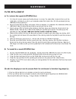
Pre-fi lter Check / Replacement

A.  To check the Pre-fi lter:

1.  Look through the sash to the inside of your unit. The pre-fi lter and pre-fi lter grid are located at the back of 

the unit.

2.  Look through the slats on the pre-fi lter grid. If the prefi lter is discolored (the original color is green), 

replacement is needed.

B.  To replace the Pre-fi lter:

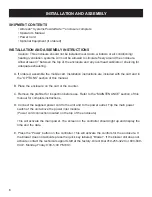
1.  Don the proper PPE for handling the substance that have been used inside the hood (refer to the MSDS 

sheets).  

2.  Turn the unit on and make sure that the blower is running.

3.  Place an appropriate poly bag on the base of the enclosure. You will place the saturated pre-fi lter inside 

the bag and seal it before removing it from the hood.

4.  Remove the 4 black knobs or 6 polypropylene clips that hold the prefi lter grid in place. This will expose 

the clogged pre-fi lter. Do not remove the pre-fi lter from the hood!

5.  Remove the pre-fi lter from the pre-fi lter grid and place it inside the poly bag. Wipe any residue off of the 

pre-fi lter grid and base of the enclosure. Place the rag inside the bag with the pre-fi lter and seal the bag. 

Dispose of the pre-fi lter in accordance with your local guidelines for the substances that have been used 

inside the hood.

6.  Inspect the HEPA fi lter for blockage. If replacement is needed, refer to the “FILTER REPLACEMENT” 

Type B, sub-section of this manual for complete instructions.

7.  Place the new pre-fi lter into the pre-fi lter grid and secure into place with the 4 black knobs or 6 

polypropylene clips.

8.  Dispose of your PPE in accordance with your local guidelines for the substances that have been used 

inside the hood.

MAINTENANCE

Содержание POWDERSAFE 760C

Страница 1: ...6120 Website www aircleansystems com Email info aircleansystems com Product designs are subject to change without notice 2005 AirClean Systems Inc ACOM03600PS C OPERATOR S MANUAL POWDERSAFE DUCTLESS...

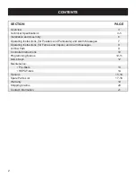
Страница 2: ...d Particulate and Alarm Messages 7 Operating Instructions for Fumes and Vapors and Alarm Messages 8 Air ow Path 9 Controller Instructions 10 Programming Menus 10 11 Quick Keys 12 Maintenance Pre lters...

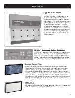
Страница 3: ...st AirClean Systems has eliminated this problem with breakthrough bonded carbon technology Bonded carbon lters are solid blocks of activated coconut shell carbon held in a solid and predictable matrix...

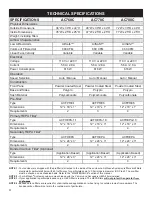
Страница 4: ...18 x 3 Requirements 2 3 4 Secondary HEPA Filter3 Type ACFHEPA ACFHEPA ACFHEPA Dimensions 12 x 24 x 3 12 x 24 x 3 12 x 24 x 3 Requirements 2 3 4 Bonded Carbon Filter4 ilter4 ilter Optional Type Applica...

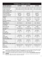
Страница 5: ...3 Requirements 2 3 4 Secondary HEPA Filter3 Type ACFHEPA ACFHEPA ACFHEPA Dimensions 12 x 24 x 3 12 x 24 x 3 12 x 24 x 3 Requirements 2 3 4 Bonded Carbon Filter4 ilter4 ilter Optional Type Application...

Страница 6: ...Place the enclosure on the cart or the counter C Remove the pre lter for inspection before use Refer to the MAINTENANCE section of this manual for complete instructions D Connect the supplied power co...

Страница 7: ...particulate inside your enclosure B When working within the enclosure keep the front sash down and perform your procedure in the center to rear of the enclosure C If the low air ow alarm sounds and or...

Страница 8: ...substances please call our of ce to verify compatibility before use in this case your lter may have another model number Direct Dial 919 255 3220 or 800 849 0472 Monday Friday 8 00 5 00 PM EST 2 Conne...

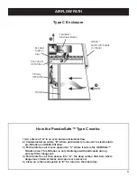
Страница 9: ...rostatic pre ltration and HEPA ltration 3 Particulate free air moves upward to C where it enters the HEPASafe ltration area This ltration is only challenged with particulate during primary lter change...

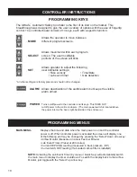
Страница 10: ...m armed POWER Turns on off power to the controller and its keys This DOES NOT cut off power to the entire enclosure The main power switch is located above the power inlet on the back right hand side o...

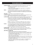
Страница 11: ...ible alarm when it sounds by touching the alarm button on the controller The visible alarm will still work FILTER This menu shows the serial number and the purchase date of the lter For every new lter...

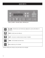
Страница 12: ...tive key for enclosure LIGHT One touch to enable uorescent light if installed TIMER User de nable lab event timer AUX Inactive key for enclosure Figure 6 AirSafe automatic safety controller layout ont...

Страница 13: ...your unit The pre lter and pre lter grid are located at the back of the unit 2 Look through the slats on the pre lter grid If the pre lter is discolored the original color is green replacement is need...

Страница 14: ...x nuts and remove the lter hold down 6 Place the spent HEPA lter into the second poly bag Wipe any residue off of the lter hold down frame and any other obvious areas Place the second rag into the bag...

Страница 15: ...cart is completely assembled 3 Repeat steps above for holes 2 and 3 4 For standard setup complete assembly using hole 4 For seated use complete assembly using hole 5 5 Tighten all bolts completely 6...

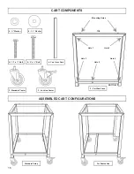
Страница 16: ...Cross Piece 2 Locking Caster 2 Standard Caster 4 Washer 8 1 Washer 4 1 x Bolt 8 2 x Bolt Standard Setup For Seated Use Mounting Holes Hole 3 Hole 5 Hole 4 Hole 1 Hole 2 ASSEMBLED CART CONFIGURATIONS...

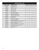
Страница 17: ...orescent Fixture 30w 1 10 50428 Fuse 6 3a 250V Slo Blo 1 1 1 06 50481 Gas Strut 60 2 2 06 51087 Gas Strut 90 2 06 50012 Hinge Door Positioning 6 8 12 06 50053 Hinge Medium Black 3 4 5 11 52756 Keypad...

Страница 18: ...orescent Fixture 30w 1 10 50428 Fuse 6 3a 250V Slo Blo 1 1 1 06 50481 Gas Strut 60 2 2 06 51087 Gas Strut 90 2 06 50012 Hinge Door Positioning 6 8 12 06 50053 Hinge Medium Black 3 4 5 11 52756 Keypad...

Страница 19: ...tems or the dealer who sold y ou the product If the cause is determined to be a manufacturing fault the dealer or AirClean Systems will repair or replace all defective parts to restore the unit to ope...

Страница 20: ...eturn any materials without authorization from AirClean Systems Systems Products returned without prior authorization will not be accepted AirClean Systems Systems and its dealers are not responsible...

Страница 21: ...04 Phone 919 255 3220 Toll Free 800 849 0472 Fax 919 255 6120 Visit AirClean Syste Syste ms on the Internet at http www aircleansystems com Email AirClean Systems at Systems at info aircleansystems co...

Страница 22: ...gh NC 27604 Phone 919 255 3220 Toll Free 800 849 0472 Fax 919 255 6120 E mail info aircleansystems com Product designs are subject to change without notice 2005 AirClean Systems Inc Systems Inc ACOM03...

Отзывы: