


Manual E
0905e
EDITION 2010
Pneumatic Actuators
MANUAL
Modifications reserved. Date 06.2011.
No guarantee for accuracy.
Older data sheets are invalid.
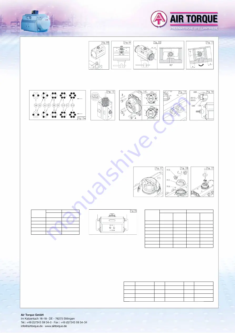
C.
End cap (Part N° 30) assembly,
fi gures 12, 13 and 14:
•
Assemble one end cap at a time.
•
Lubricate the body.
•
For spring return actuators, insert the springs in
each end cap according to the desired con-
fi guration, as shown in fi gure 12 and related
tables. For models DRSC00030U -> DRSC5000U
insert spring cartridges as shown in fi gure 13.
•
Fit end cap o-ring seal (14) into the groove on both end caps.
•
Fit end caps onto the body (50), verifying that the o-ring remains in the groove.
•
Only for actuators with 50% or 100% stroke adjustment, ensure that the adjustment screws 221G/222G are completely screwed into the end-cap.
•
Insert the cap screws (13) and tighten each only partially. Complete tightening by making 1-2 turns for each screw in the sequence shown in fi gure 14
until tightening is completed. See the table for screw tightening torque.
D.
Assembly of stop cap screws (Part 02) and stroke adjustment for models DRSC00015U -> DRSC5000U, fi gures 15 and 16:
•
Fit the stop cap screws (02) in the body.
•
Stroke adjustment for actuators with standard type “ST” rotation / assembly (clockwise to close).
Stroke adjustment in close position: with the actuator in close position 0°, screw or unscrew the right (from top view) stop cap screw until the desired
stop position is achieved. Then tighten the stop adjustment nut (04) to lock it in place.
Stroke adjustment in open position: with the actuator in open position 90°, screw or unscrew the left (from top view) stop cap screw until the desired
stop position is achieved. Then tighten the stop adjustment nut (04) to lock it in place.
For spring return actuators, it could be necessary to make rotation tests to verify the correct stroke adjustment in open position.
•
Only for actuators with adjustment 50% or 100%, fi t on end-cap adjustment screws 221G/222G the o-rings 11R, the washers 03R and the nuts 04R.
To adjust the stroke in open position: with the actuator in partially or totally open position, screw or unscrew the end-cap adjustment screw 221G/222G
until the desired position is achieved.
It is important that the two end-cap adjustment screws are both in contact with the pistons. Then lock the nuts 04R.
E.
Assembly of graduated ring and position indicator (Part N° 19,19.0,19.1), fi gures
17,18 and 19:
•
Fix the graduated ring (19.0) to the body.
•
If necessary, correctly position the “Top Adaptor” (19.5) and lock it with the proper
screws (19.6).
•
Insert the indicator (19 or 19.1) making sure that it indicates the correct actuator
position.
•
Screw the indicator screw (39) if assembled.
Spring Set
Side B
Side A
DRSC00010U
Spring type
DRSC00010U
Spring type
S1-1
1 (green)
1 (green)
S1-2
1 (green)
2 (red)
S2-2
2 (red)
2 (red)
S2-3
2 (red)
3 (black)
S3-3
3 (black)
3 (black)
Spring Set
Side B
Side A
DRSC00015U
Internal
spring type
DRSC00015U
External
spring type
DRSC00015U
Internal
spring type
DRSC00015U
External
spring type
S1
1 (green)
-------
-------
2 (black)
S2
-------
2 (black)
-------
2 (black)
S3
-------
2 (black)
-------
3 (red)
S4
-------
3 (red)
-------
3 (red)
S5
-------
3 (red)
1 (green)
2 (black)
S6
1 (green)
2 (black)
1 (green)
2 (black)
S7
1 (green)
2 (black)
1 (green)
3 (red)
S8
1 (green)
3 (red)
1 (green)
3 (red)
Tab.01: Spring set confi guration DRSC00010U
Tab.02: Spring set confi guration DRSC00015U
Spring set confi guration of SC/SO00010U and SC/SC00015U:
Side A
Side B
Side A
Side B
7. STORAGE
INSTRUCTIONS
If the actuator is not for immediate use, the following precaution must be taken for storage:
•
Store the actuator in a clean and dry environment and at temperature between –20°C (-4°F) and +40°C (+104°F).
•
It is recommended that the actuator be stored in its original box.
•
Do not remove the plastic plugs on air supply ports.
8.
LIFTING and HANDLING
It is recommended to lift the actuators with proper, adequate and permitted systems in relation to the actuator weight and by following the ruling laws
in terms of safety and health protection. The weight of the actuators is indicated on the Air Torque catalogue and on the related technical data-sheets.
During the lifting and the handling of the actuators, it is recommended to avoid clashes and/or accidental falls in order to avoid irreparable damages
to the actuators and to compromise the functionality.
Contact Air Torque for any information and technical data-sheets.
9.
NOTES regarding the FLANGE CONNECTION
Extract from the standard DIN ISO 5211:
The torque values in the following table show the maximum torques which
are allowed to be transmitted by the flange connection:
Flange
Md max.all. (Nm)
Flange
Md max.all. (Nm) Flange Md max.all. (Nm)
F03
32
F10
500
F25
8 000
F04
63
F12
1 000
F30
16 000
F05
125
F14
2 000
F07
250
F16
4 000


