


Tightening torque table:
M..
Nm
M5
5 -> 6
M6
10 -> 11
M8
23 -> 25
M10
48 -> 52
M12
82 -> 86
M14
132 -> 138
M16
200 -> 210
M20
390 -> 410
M24
675 -> 705
M30
1340 -> 1400
Manual E
0902e
EDITION 2010
Pneumatic Actuators
MANUAL
Modifications reserved. Date 06.2012.
No guarantee for accuracy.
Older data sheets are invalid.
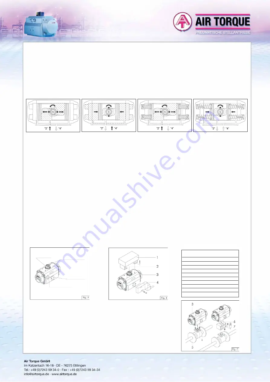
Air supplied to port 2 forces the pistons
towards the actuator end caps. A counter-
clockwise rotation is achieved. Exhaust air
exits from Port 4.
Air supplied to Port 4 forces the pistons
inward. A clockwise rotation is achieved.
Exhaust air exits from Port 2.
Double Acting operation function (standard rotation type “ST”) TOP View
Air supplied to Port “2” forces the pistons
toward the actuator end caps, compressing
the springs. A counter-clockwise rotation is
achieved. Exhaust air exits from Port 4.
The loss of air pressure (air or electric failure)
at Port “2” allows the springs to force the
pistons inward. A clockwise rotation is achie-
ved. Exhaust air exits from Port 2.
Single Acting operation function (standard rotation type “ST”) TOP View
5. ACTUATOR
INSTALLATION
INSTRUCTIONS
The Air Torque actuator is a pneumatic device for the remote operation of industrial valves. The actuator will operate through 90°,120°,135° and 180° rotation
permitting the opening and closing of many types of valves up to 180° rotation.
All the necessary technical information to install the actuator correctly and safely onto a valve i.e.: Dimensions, Output torque, Supply pressure, Air volume,
Stroke adjustment, Operating time, Operating temperature, Direction of rotation and Weight is stated clearly on the Actuator label, in the catalogue and
technical data sheets. Please read all technical information before proceeding with the actuator installation.
5.1 Important
safety
notice!
•
For safety reasons, the actuator must not be pressurized at any time during installation as injury may result.
•
The utmost cleanliness is required during air supply connection to the actuator i.e. the connecting pipe thread, fittings and seals must be clean and dirt-free.
•
When fitting accessories onto the actuators, assemble them in such a way that the emergency control of the solenoid valve and the top of the drive
shaft are easily accessible, should emergency manual operations be required.
•
Before fitting onto the valve, make sure that the actuator/valve are correctly orientated, depending upon which direction of rotation is required.
•
For spring return actuators, avoid that dangerous and/or corrosive substances in the working environment enter into the external chambers by using
adequate filters and/or solenoid valves.
•
Remove plugs from actuator air connections during installation and operation. Protect the air connections of actuators not being used immediately.
5.2
Interfaces for actuator control and connections, figure A:
5.3
Assembly of accessories: Solenoid valves and switchboxes, figure B:
• Solenoid
valve
mounting:
Before mounting a solenoid valve, ensure that the actuator is in its normal position (closed position) with pistons inwards.
For standard rotation type “ST” (clockwise to close) assembly: the groove on the drive shaft or on the position indicator 2 must be horizontal to the
longitudinal axis of the actuator in closed position.
Fit the solenoid valve 4 onto the actuator 3 using the provided screws (max. tightening torque see table).
• Switchbox
mounting:
Fit the switchbox and bracket 1 onto the actuator 3 using four provided screws (max. tightening torque see table).
5.4
Assembly of valve figure C:
Before proceeding with the assembly of the actuator onto the valve, be sure that the actuator operates
in the desired direction of rotation when pressurised and both actuator / valve are in the correct posi-
tion.
Important: when using a spring return actuator for a fail safe operation, ensure that when air or electri-
city failure occurs the direction of rotation is correct for your application.
Fit the actuator 3 onto the valve 5. It is possible to assemble the valve onto the actuator in two ways:
•
Direct-mount: fit the stem of the valve 5 directly into the female connection of the actuator 3 and bolt
together through the valve ISO pad (max. tightening torque see table).
•
Bracket-mount: mounting with a bracket 6 and coupling 7, the bracket is bolted to the actuator / valve
to join them together and the coupling is used to connect the actuator output drive to the valve stem
(max. tightening torque see table).
4.
OPERATING FUNCTION AND DIRECTION OF ROTATION
The actuator is a pneumatic device for remote operation of industrial valves. The operation (90°,120°,135° or 180° rotation) may be activated by different
methods:
•
Direct mounting of solenoid valve (5/2 for double acting, 3/2 for spring return) to pressure connections 2 and 4, connected to supply and control lines.
•
Screwed connection (to pressure connections 2 and 4) with air lines from separate control cabinet. The standard rotation (when port 4 is pressurized or
for spring action) is clockwise to close. When port 2 is pressurized, counter-clockwise rotation is obtained.
Air Torque actuators can be supplied with different types of assembly/rotation direction depending on the type of required operation and/or installation,
see technical data sheets.
Position indicator
VDI/VDE 3845
Ancillaries
attachment
VDI/VDE 3845
Pressure
connection
ISO5211 / DIN 3337
Valve actuator attachment


