background image

12

MN-831

LoadLifter 5000 Ultimate

INSTALLING THE HEAT SHIELD

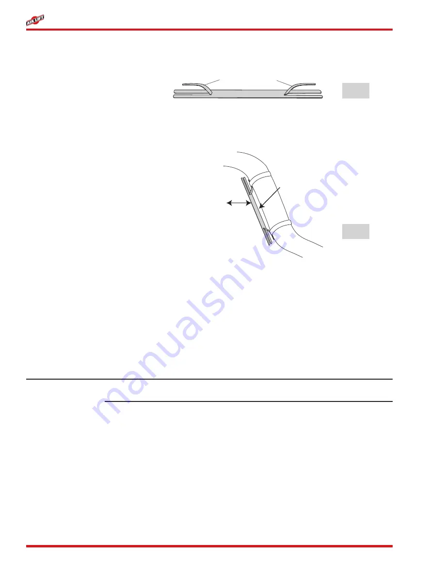
1.  Bend tabs to provide a 1/2” dead air space between exhaust pipe and heat shield (Figure 

13).

NOTE

Bend Tabs Up

fig. 13

fig. 14

2.  Attach the heat shield (Q) to the exhaust pipe using the clamps (R) (Figure 14).  Bend 

the heat shield for maximum  clearance to the air spring.

Distance from Heat 

Shield to Bellows 

must be at least ½"

At least ½"

of dead air 

space

3.  On the driver side, it will be necessary to secure the emergency brake cable away from 

the air spring to prevent it from rubbing.  Use the provided tie straps (BB).

CHECKING FOR LEAKS

1.  Inflate the air spring to 60 p.s.i.  
2.  Spray all connections and the inflation valves with a solution of 1/5 liquid dish soap 

and 4/5 water to check for leaks.  You should be able to spot leaks easily by looking for 

bubbles in the soapy water.  

3.  After the test, deflate the springs to the minimum pressure required to restore the Normal 

Ride Height, but not less than 5 p.s.i.

Check the air pressure again after 24 hours.  A 2 to 4 p.s.i. loss after initial installation is 

normal.  Retest for leaks if the loss is more than 5 lbs.

FIXING LEAKS

1.  If there is a problem with the swivel fitting, then:
a.  Check the air line connection by deflating the spring and removing the line by pulling the 

collar against the fitting and pulling firmly on the air line.  Trim 1” off the end of the air 

line.  Be sure the cut is clean and square.  Reinsert the air line into the push-to-connect 

fitting.

b.  Check the threaded connection by tightening the swivel fitting another 1/2 turn.  If it 

still leaks, deflate the air spring, remove the fitting, and re-coat the threads with thread 

sealant.  Reinstall by hand tightening as much as possible, then use a wrench for an 

additional two turns.

2.  If there is a problem with the inflation valve, then:

a.  Check the valve core by tightening it with a valve core tool.

Содержание LoadLifter 5000 88128

Страница 1: ...o read these instructions can result in an incorrect installation MN 831 021306 ECR 7668 INSTALLATION GUIDE ADJUSTABLE AIR HELPER SPRINGS TOW AND HAUL WITH SAFETY AND COMFORTTM safety please read thes...

Страница 2: ......

Страница 3: ...nstalling the Frame Brace 9 Installing the Air Lines 10 Installing the Heat Sheild 12 Checking For Leaks 12 Fixing Leaks 12 Before Operating 13 Installation Checklist 13 Post Installation Checklist 13...

Страница 4: ...tact Air Lift Company at 800 248 0892 or visit our website at www airliftcompany com IMPORTANT SAFETY NOTICE The installation of this kit does not alter the Gross Vehicle Weight Rating GVWR or payload...

Страница 5: ...LoadLifter 5000 Ultimate Installation Diagram INBOARD FORWARD OPTION see Figures 4 6 A B C D E F G N O H H I I I H J K J J J J K K J J M M N O O O O E P KIT 88216 A KIT 88128 NOTE No roll plates are u...

Страница 6: ...rts AA Air Line Assembly 1 BB Tie Strap 6 CC Valve Caps 2 DD 5 16 Flat Washer 2 EE Rubber Washer 2 FF Small Star Washer 2 GG 5 16 Hex Nut 4 not shown in Figure 1 Description Qty 7 16 9 16 open end or...

Страница 7: ...used off road COMPRESSED AIR CAN CAUSE INJURY AND DAMAGE TO THE VEHICLE AND PARTS IF IT IS NOT HANDLED PROPERLY FOR YOUR SAFETY DO NOT TRY TO INFLATE THE AIR SPRINGS UNTIL THEY HAVE BEEN PROPERLY SEC...

Страница 8: ...t then place axle stands under the axle and raise the frame as needed c If the vehicle is raise with a jack and supported with axle stands on the frame then use a floor jack to lower the axle REMOVING...

Страница 9: ...ost 1 ton single rear wheels and some 1 ton dual rear wheel trucks take the stack in Figure 5 Most 1 ton dual rear wheel trucks take the stack in Figure 6 For and ton trucks and some 1 ton trucks with...

Страница 10: ...of the lower bracket Figure 8 6 Set a roll plate E on both ends of the double convolute bellow Figure 1 Kit 88128 with the single convolute bellow does not require roll plates 7 Set the bellow assemb...

Страница 11: ...a template center punch and drill a 3 8 hole through the outboard side of the frame rail and upper bracket Figure 9 CAUTION Use hole in upper bracket as a template to center punch and drill 3 Install...

Страница 12: ...flanges b License plate recess in bumper c Under the gas cap access door d Through license plate itself What ever the chosen location is make sure there is enough clearance around the inflation valves...

Страница 13: ...haust pipes muffler or catalytic converter Avoid sharp bends and edges Use the plastic tie straps BB to secure the air line to fixed non moving points along the chassis Be sure that the tie straps are...

Страница 14: ...3 After the test deflate the springs to the minimum pressure required to restore the Normal Ride Height but not less than 5 p s i Check the air pressure again after 24 hours A 2 to 4 p s i loss after...

Страница 15: ...e eliminated before the vehicle is road tested Heat test Be sure there is sufficient clearance from any heat sources at least 6 for air springs and air lines If a heat shield was included in the kit i...

Страница 16: ...minimum air spring pressure will void the Air Lift warranty 5 When increasing load always adjust the air pressure to maintain the normal ride height Increase or decrease pressure from the system as n...

Страница 17: ...last indefinitely Q Will raising the vehicle on a hoist for service work damage the air springs No The vehicle can be lifted on a hoist for short term service work such as tire rotation or oil change...

Страница 18: ...ed that the air bags have bottomed out increase the pressure fig 2 4 5 Adjust the pressure up and down to find the best ride 6 If the vehicle rocks and rolls adjust the air pressure to reduce movement...

Страница 19: ...ressor will work well for most customers who use their system on an intermittent basis Heavy duty For daily use consider the heavy duty compressor it inflates faster and more quietly than the standard...

Страница 20: ...Company for verification Air Lift will repair or replace at its option defective products or components A minimum 10 00 shipping and handling charge will apply to all warranty claims Before returning...

Страница 21: ...tailer where the kit was purchased If it is necessary to return or exchange the kit for any reason If there is a problem with shipping if shipped from the retailer If there is a problem with the price...

Страница 22: ......

Страница 23: ......

Страница 24: ...irliftcompany com Thank you for purchasing Air Lift products the professional installer s choice Printed in the USA Need Help Contact our customer service department by calling 800 248 0892 Monday thr...

Отзывы: