


6727924 Rev. G 4/22
3 of 12
www.airkinglimited.com
2. Pull the loose black, white and green wires out from the wire compartment (additional wires
will be present). Install an approved electrical connector to the wire compartment cover (not
included). Run a black (hot), white (neutral), and a green or bare ground wire from the supply
through the electrical connector. Connect all wires from the supply to their corresponding
wires within the wire compartment
(Figure 6)
. Use approved methods for all connections.
3. Carefully tuck wires back inside wire compartment and replace wire compartment cover
securing with the screw that was removed earlier.
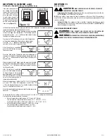
SECTION 5
Setting the Speed
1. Remove the screws securing the access panel cover in place and open the cover to gain
access. Locate the speed control panel inside the unit
(Figure 7).
2.
Determine the CFM required. The unit can be
set from 30 CFM to 130 CFM in increments of
10 CFM
(Figure 8).
SECTION 6
Motorized Damper
An optional motorized damper can be connected to the unit.
The damper is connect via a 24V transformer that plugs into the
receptacle in the unit
(Figure 9)
.
NOTE:
Make sure to reference the instructions included with
the motorized damper before installing or operating.
Operation
1.
When installed the outlet will be energized anytime
the unit is running. This will in turn open the damper.
When the unit stops running, the damper will close.
SECTION 7
Optional Air Filter
An air filter (available separately) can be added to this unit to provide additional filtration of the
intake air. The unit will accept a 10
"
x 10
"
x 2
"
filter. To install:
NOTE:
Adding an air filter will decrease the airflow of the unit. You will need to increase the CFM
selected in
SECTION 5
to account for the decreased air flow. Filters must be changed regularly. Refer
to the filter manufacturer’s recommendations to determine how often the filter should be changed.
1.
Remove the screws securing the access panel cover in place and open the cover to gain
access to the controls and filter area.
2.
Ensure the filter is facing the correct way and slide the filter into the slot in the housing.
Make sure the filter is seated all the way to the bottom of the housing
(Figure 10).
3.
Close the access panel and reinstall the screw holding the access panel in place.
Figure 6
Supply from house
Black
Neutral (White)
Ground (Green or Bare)
Fa
n
Neutral (White)
Green
Black
Green
By others
Figure 7
Screw
Screw
Figure 9
Receptacle
Figure 10
Filter
Screw
Air Flow
Screw
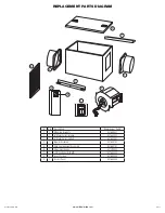
SECTION 8
Completing the Installation
NOTE:
When fan is mounted inline and no penetration is made into unconditioned spaces, there
is no need to use a sealant appropriate for contact with the building materials present and for the
temperature requirements of the installation to prevent air leakage from unconditioned spaces.
Additional material (backing rod, ceiling material) are also not required.
NOTE:
This unit is equipped with a wire mesh insect screen. Confirm that the screen is installed
on the inside of the unit on the inlet ducting side.
1.
If the screen is not in place, insert the screen into the tab at the base of the unit (make sure
the wider side of the screen is running side to side inside the unit)
(Figure 11).
2.
Slide the screen to the side with the larger top tab making sure the screen fits behind the
tab
(Figure 11).
3.
Slide the screen back over towards the smaller top tab making sure the screen fits behind
the tab
(Figure 12).
4.
Confirm that the screen is being held in place by both top tabs
(Figure 12).
5.
Close the access panel and reinstall the screws holding the access panel in place.
6.
Restore power and test your installation.
SECTION 9 (QFAMD only)
Using the Controller
1.
On Mode:
Fan will run continuously when the ON button (
) is pressed. If ambient
temperature is lower than 34°F (2°C), the fan will stop and initiate Sampling Mode. Sampling
Mode Cycle: stop 15 mins; run for 5 minutes to determine current air temperature. During
Sampling Cycle, if the temperature is in the accessory heater (optional) control range, the
heater will turn on (if it has been installed). The fan will return to continuous ventilation
once ambient temperature rises above 34°F (2°C).
2.
Energy Savings Mode:
To enter the Energy Savings mode, press the Energy Savings
button (
) until appears on the left side of the display. Energy Savings mode
engages the settings configured in
SECTION 10
. When the unit is on, the display will
show the current conditions (temperature and humidity level) as well as if it is in Energy
Savings mode or not. Other icons/information that may be on the display include:
Fan icon appears when the fan is on.
“HI°F” appears if the intake temperature is above 150°F (65°C).
“Lo°F” appears if the intake temperature is below 15°F (-10°C).
“Lo%” appears if the intake humidity is below 10%.
3.
Optional Heater Unit:
An optional heater unit is available for climates that the air coming into
the unit falls below 54°F (12°C). To install the unit, follow the directions that are included with
that unit. The display will show a thermometer icon with either a “1”(
1
) or “1 2” (
1
2
) when
the temperature range is at a level where the heating element would come on if present.
Stage 1 - “1” turns on when the intake air temperature is between 39°F (4°C) and 54°F
(12°C). Stages 1 and 2 “1 2” turn on when the intake air temperature is between 33°F (0°C)
and 39°F (4°C).
Figure 11
Base Tab
Screen
Larger
Top Tab
Figure 12
Screen
Smaller Top Tab
Screen
Figure 8
30
4
0 50 60 70
8
0
90
1
00 1
10
120
13
0


