


6727924 Rev. G 4/22
2 of 12
www.airkinglimited.com
INSTALLATION INSTRUCTIONS
CAUTION:
MAKE SURE POWER IS SWITCHED OFF AT SERVICE
PANEL BEFORE STARTING INSTALLATION.
SECTION 1
Preparing the Fan
1.
Unpack fan from the carton and confirm that all pieces are present. In addition to the fan
you should have:
2 - Collar Assembly (attached)
2 - Mounting Brackets (attached)
1 - Controller (attached) (QFAMD Only) 1 - Instruction/Safety Sheet
2. Choose the location for your fan. To ensure the best air and sound performance, it is
recommended that the length of ducting and the number of elbows be kept to a minimum,
the radius of each elbow be as large as possible for the installation, and that insulated hard
ducting be used. This fan will require at least 12” of clearance in the ceiling or wall. The fan
mounts using the provided mounting brackets or can be surface mounted to a wall or ceiling.
NOTE:
The fan must be installed into a location that can be easily accessed once installed.
3.
No additional vibration deadening materials are needed for this fan.
SECTION 2
Mounting the Fan
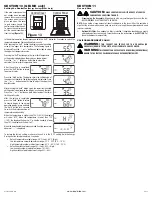
1.
Confirm the fan is positioned so the air flow is in the correct direction.
2a.
Surface Mounting:
Locate at least one stud or joist. Place the fan in position so that the
mounting bracket is centered on the stud or joist and make the location for the four (4)
holes. Remove the fan and install properly rated wall/ceiling anchors for the holes that do
not go directly into a joist or stud. Position fan in place and secure with screws (not
included)
(Figure 1).
2b.
Mounting to a Joist:
Install two - 2 x 4 headers (not included) between the joists. Position
the fan housing on top of the headers and secure the mounting brackets with screws (not
included) to the header
(Figure 2)
.
2c.
Hanging Bar Mounting:
Lift unit up onto the threaded rods and secure in place using
appropriate hardware (not included)
(Figure 3).
Figure 1
Screws
Stud/Joist
Anchor
Air Flo
w
Figure 2
Joist
2 x 4 Header
Bracket
12"
Figure 3
Bracket
Housing
Threaded Rod
SECTION 3
Ducting
NOTE: 6” OR LARGER RIGID DUCT IS RECOMMENDED FOR BEST PERFORMANCE.
CAUTION:
ALL DUCTING MUST COMPLY WITH LOCAL AND NATIONAL
BUILDING CODES.
NOTE:
The ducting from this fan to the outside of the building has a strong effect on the air
flow, noise and energy use of the fan. Use the shortest, straightest duct routing possible for
best performance, and avoid installing the fan with smaller ducts than recommended. Insulation
around the ducts can reduce energy loss and inhibit mold growth. Fans installed with existing
ducts may not achieve their rated air flow.
WARNING:
MAKE SURE THE FRESH AIR INTAKE PORT COMPLIES WITH
ALL LOCAL AND NATIONAL CODES AND IS LOCATED AT LEAST 6 FEET AWAY
FROM SOURCES OF CONTAMINATION SUCH AS BUT NOT LIMITED TO: DRYER,
FURNACE OR CENTRAL VACUUM EXHAUSTS, GAS APPLIANCES SUCH AS BBQ GRILLS,
GARBAGE BINS OR OTHER EXHAUST PORTS.
NOTE:
To ensure quiet operation of in-line and remote fans, each fan shall be installed using sound
attenuation techniques appropriate for the installation. This can typically be achieved by installing
insulated flexible ducting between the exhaust or supply grille(s) and the fan.
1.
Connect the ducting to the fan’s duct collar
(Figure 4).
Seal ducting to housing with
appropriately rated tape. Use screws or suitable clamps to secure in place. Make sure the
fresh air intake is connected to a properly installed intake port that is a suitable weather
hood with insect screen to protect air intake. It is recommended that low restriction
termination fittings be used.
2.
Ensure duct joints and exterior penetrations are sealed with caulk or other similar material
to create an air-tight path to minimize building heat loss or gain and to reduce the potential
for condensation. Place/wrap insulation around duct and/or fan in order to minimize possible
condensation buildup within the duct, as well as building heat loss or gain.
NOTE:
At the base of the duct adapter, there is a small diameter test port hole covered with a
plastic cap. Make sure the test port is not covered up with the ducting so that it can be accessed
for pitot tube testing. To access the port, remove the port cover and insert tube.
SECTION 4
Wiring
CAUTION:
MAKE SURE POWER IS SWITCHED OFF AT SERVICE
PANEL BEFORE STARTING INSTALLATION.
CAUTION:
ALL ELECTRICAL CONNECTIONS MUST BE MADE
IN ACCORDANCE WITH LOCAL CODES, ORDINANCES, OR NATIONAL
ELECTRICAL CODE. IF YOU ARE UNFAMILIAR WITH METHODS OF
INSTALLING ELECTRICAL WIRING, SECURE THE SERVICES OF A
QUALIFIED ELECTRICIAN.
NOTE:
This unit includes a side access panel for wiring that does not require the removal of the
fan’s blower assembly.
1. Remove the wire compartment cover screw and place cover in a secure place
(Figure 5).
Figure 4
Air Flow
Intake Ducting
Outlet Ducting
Test Port
Figure 5
Screw
Wire
Compartment
Cover
Ground
Screw


